SYS-CP842-1.1E.pdf - 第80页
SYS-CP842-1.1E 3.Machine System CP-842E / CP-842ME System Reference 71 Camera Monitor Settings 1. Select [Maintenance] [Configuration] [Vision Monito r] from the [Main] screen. 2. Select from [All], [4 Division ], [9 Div…
3.Machine System SYS-CP842-1.1E
70 CP-842E / CP-842ME System Reference
3.1.15 Vision System
Displaying the Vision Monitor
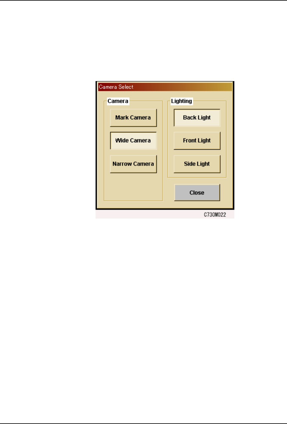
The touch screen has a built in vision monitor. Users can display the Vision Monitor and
select between the [Mark Camera], [Wide Camera] and [Narrow Camera] for the acquired
images displayed, by pressing [Vision] in the command bar. Press [Close] at this screen to
clear the Vision Monitor.
Note: During automatic operation, it is not possible to display the vision processing monitor in order to view
part images. Be sure to close the vision processing monitor before beginning automatic operation.
SYS-CP842-1.1E 3.Machine System
CP-842E / CP-842ME System Reference 71
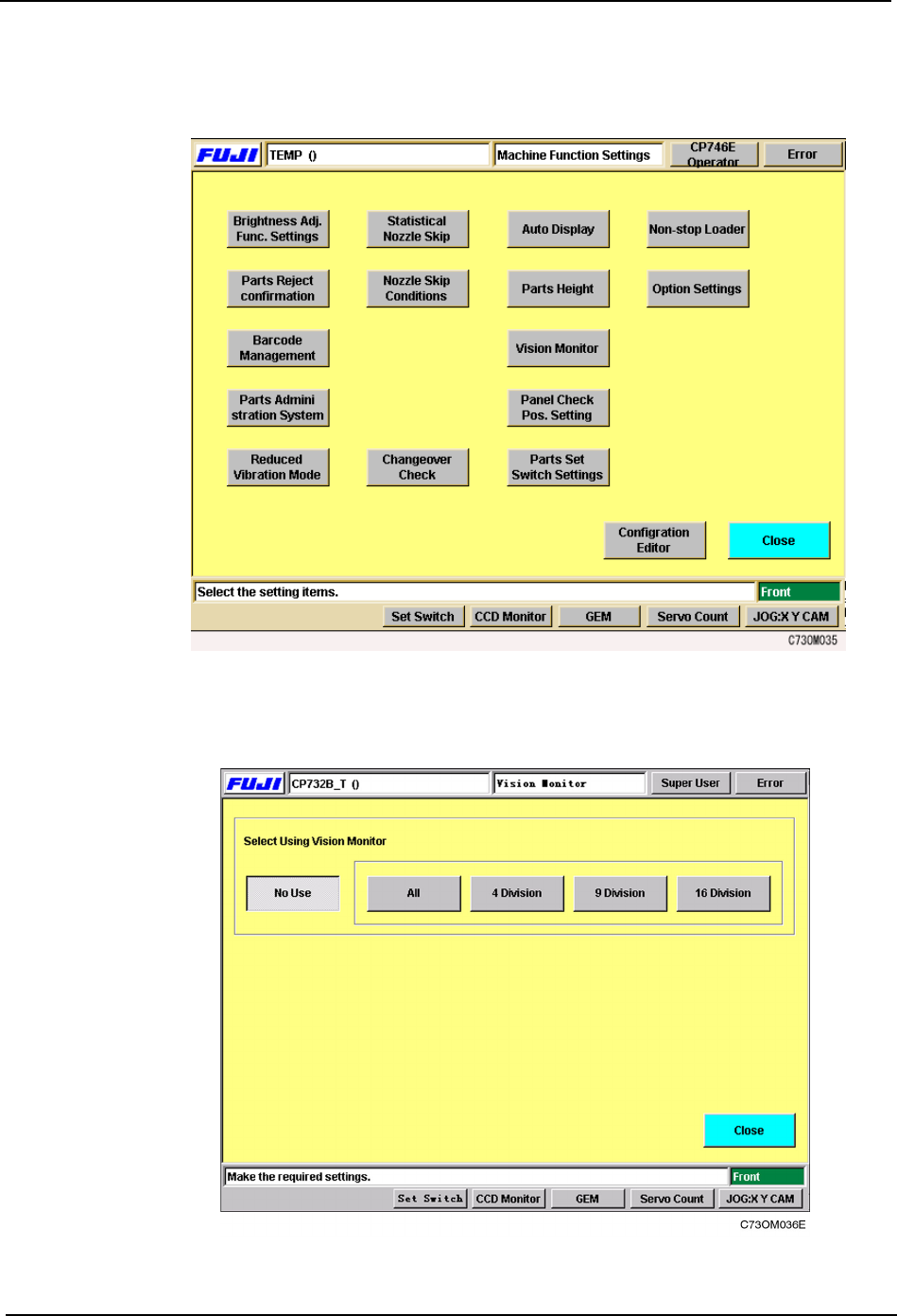
Camera Monitor Settings
1. Select [Maintenance] [Configuration] [Vision Monitor] from the [Main] screen.
2. Select from [All], [4 Division], [9 Division] or [16 Division] for the display mode at the
external vision monitor.
3.Machine System SYS-CP842-1.1E
72 CP-842E / CP-842ME System Reference
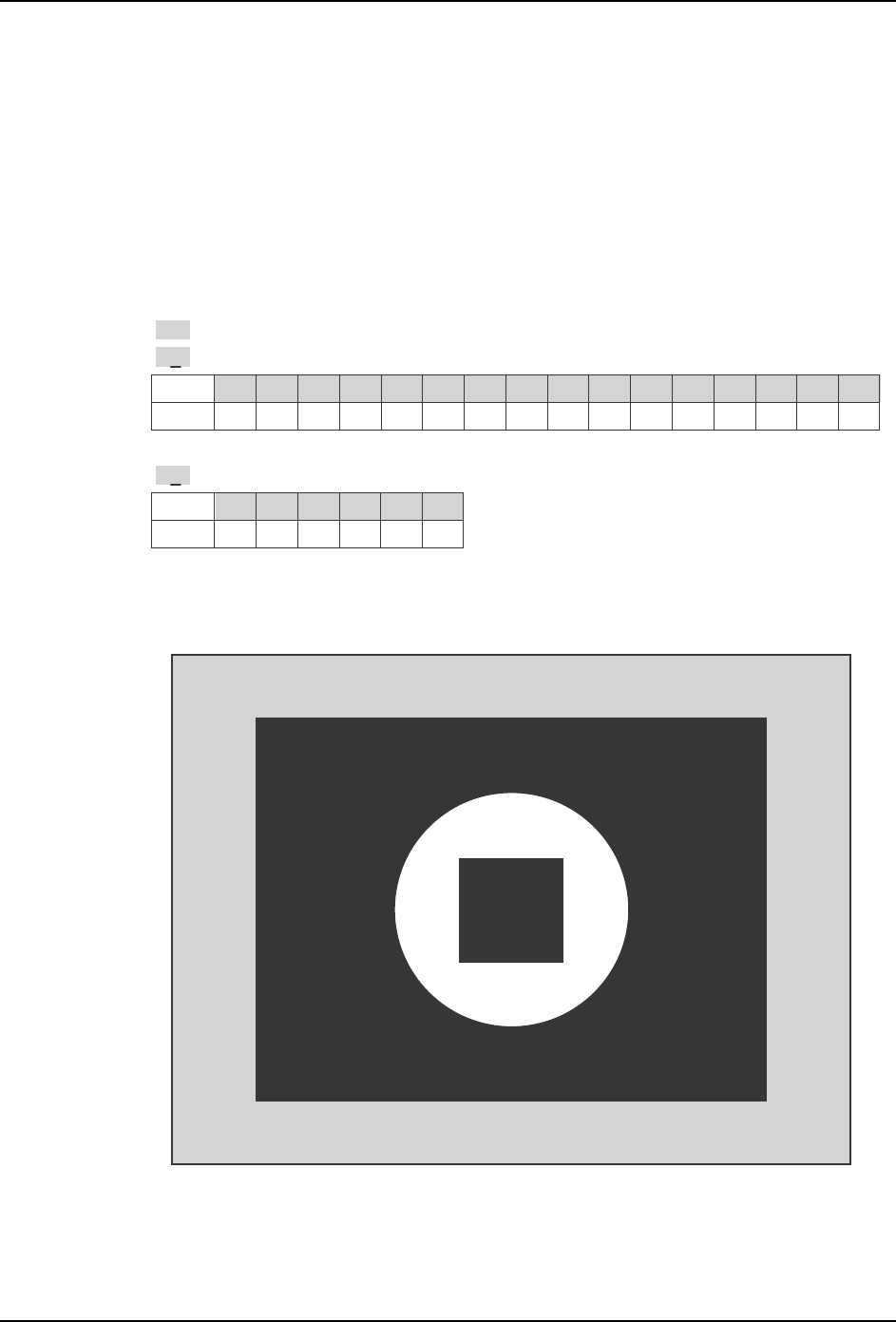
Display
Display is carried out during automatic operation, nozzle checks and PAM measurements.
Appended information for the current display is shown at the bottom left, if a cycle or
emergency stop occurs .
Note: This is not a realtime display during operation.
Description of the Appended Information
Display when [ ALL ] is selected
Display
Head
0 1 2 3 4 5 6 7 8 9 10 11 12 13 14 15
ABCDE FGH I J KLMNO
P
Display
Holder
012345
123456
.
>>
: Indicates the image is the last processed image acquired.
H8
: Indicates the image is of I-head.
N2
: Indicates the image is of holder 3.
T010E
>>
H8 N2
CP7S2023E