SYS-CP842-1.1E.pdf - 第60页
SYS-CP842-1.1E 3.Machine System CP-842E / CP-842ME System Reference 51 Setting the Device Table Mode There are four mo des of operation for the de vice tables (fee der pallets); Joint, Joint Resupply, Device Change and C…
3.Machine System SYS-CP842-1.1E
50 CP-842E / CP-842ME System Reference
3.1.6 Supply Unit Functions
Parts are supplied to the pick-up position from the two device pallets moving back and forth
on the D-axis at the rear of the CP-842E/842ME. This section describes functions related
to the supply of parts to the machine.
Loading and Unloading Device Pallets (CP-842ME Option)
The CP-842ME employ a pallet system for loading and unloading batches of feeders. Each
device pallet (device table) is loaded into the machine using the Pallet Change Unit (PCU).
The device table is moved to the production area for the supply of parts for assembly.
Commands at the machine are used to change a used device pallet with a fresh one.
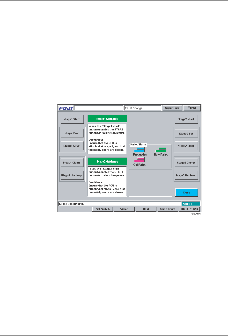
Procedure
1. At the [Main] screen, press [Change Pallet] to display the [Pallet Change] screen.
2. Select the side of the machine to be changed ([Stage 1 Start] or [Stage 2 Start]). The
START button is enabled if the PCU is docked to receive the current device table, and
the safety cover on that side is closed. If one or both of these conditions are not
satisfied, the machine displays a message telling the operator what action is necessary.
3. Press the START button to execute the changeover. The guidance area for that device
pallet describes the current operation. When the pallet is unclamped, open the safety
door and exchange device pallets using the PCU.
Note: Do not press [Close] at this screen until the changeover is complete.
4. Close the safety cover when the new device pallet is in the machine. The machine
automatically clamps the new device pallet and requests the operator to press [Stage 1
Set] ([Stage 2 set]) to complete the operation. When [Stage 1 Set] ([Stage 2 Set]) is
pressed, the device pallet is ready to be used in production. To clear the ‘Set’ status of
the pallet, press [Stage 1 Clear] ([Stage 2 Clear]).
SYS-CP842-1.1E 3.Machine System
CP-842E / CP-842ME System Reference 51
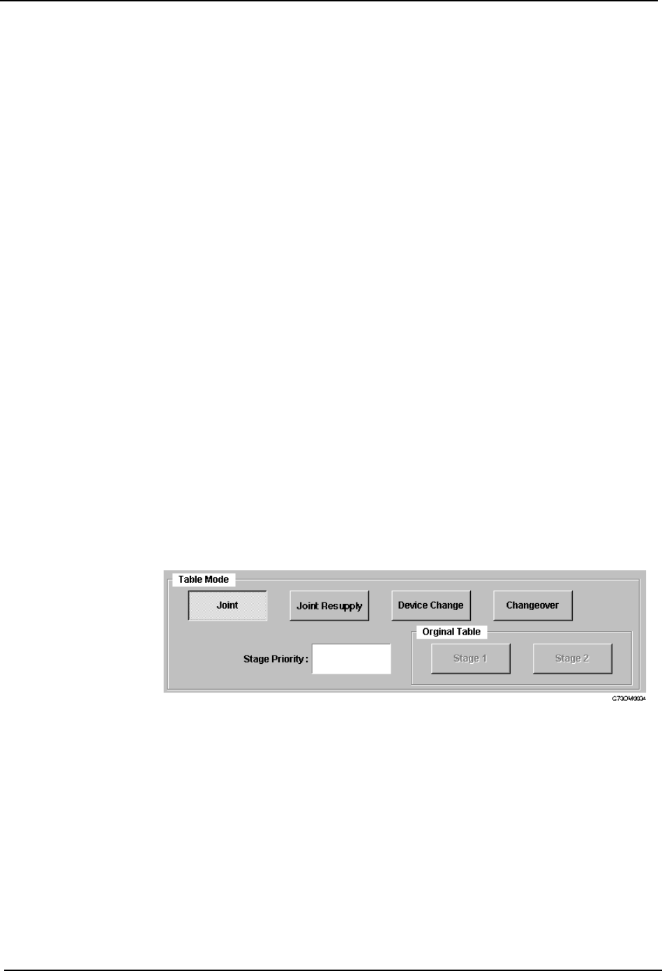
Setting the Device Table Mode
There are four modes of operation for the device tables (feeder pallets); Joint, Joint
Resupply, Device Change and Changeover.
Procedure
1. At the [Main] screen, press [Operation] to display the [Operation] screen.
2. Under Table Mode, select from [Joint], [Joint Resupply], [Device Change] or
[Changeover].
3. Press [Close] to enter the settings and return to the [Main] screen.
Joint: Joint mode is suitable for supplying a wide range of parts during
assembly. Both feeder pallets are used during production, and as a
result, up to 140 part types can be loaded on the CP-842E, and up to
80 on the CP-842ME. In this mode, both tables enter the production
area and move to the pick-up position as required.
Joint Resupply: This mode is ideal for use when the device tables are changed fairly
infrequently. Joint Resupply mode is similar to Joint mode, except
only one device table is in the production area for the majority of the
time. The follow-up table (i.e., the table which is currently idle)
remains at its retract position and does not move into the production
area until just before it is needed.
Device Change: This mode is suitable for use during mass production with a fairly
small range of parts (up to CP-842E: 70/ CP-842ME: 40 part types
on each device table). Users can create two identical feeders sets
which automatically switch places when a recovery limit on the table
currently being used is reached. The device table for which the
recovery limit was reached moves to the resupply position.
Changeover: This mode is used to reduce changeover time during small lot
production. While the current table is supplying parts for the current
assembly, the spare table can be loaded with parts for the next job.
3.Machine System SYS-CP842-1.1E
52 CP-842E / CP-842ME System Reference
Performing a Manual Device Check
Before operation can be commenced it is first necessary to inform the machine that feeders
have been correctly positioned in each of the slots that are used in the production program.
This is performed by carrying out a device check. A device check can be performed
manually or automatically, these procedures are detailed below.
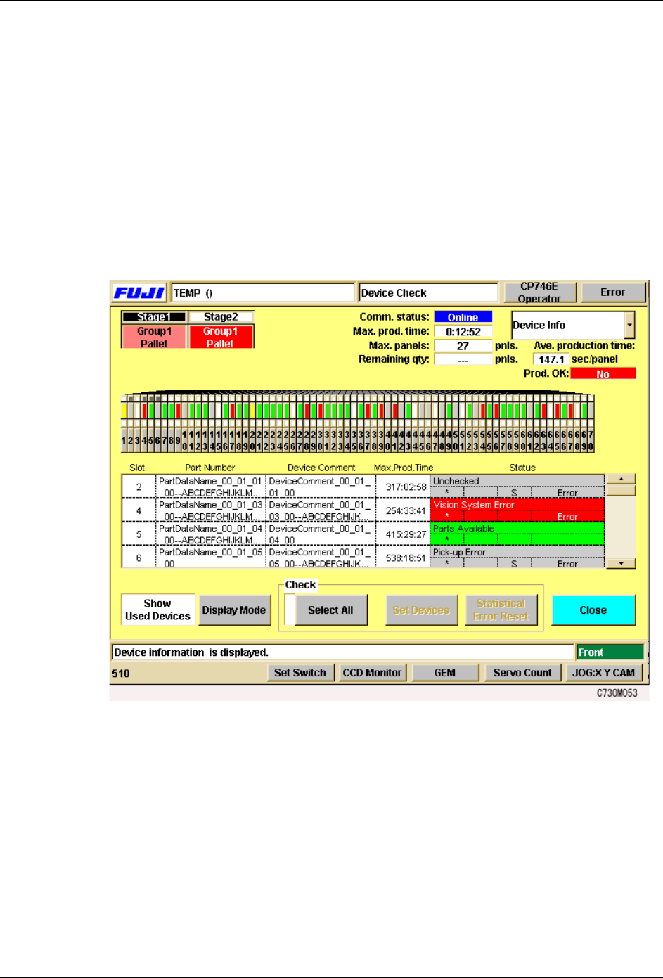
Procedure
1. Press [Device Check] at the [Main] screen. The [Device Check] screen displays.
The [Device Check] screen shows a color coded box for each of the slots on each device
pallet. An explanation of the color coding system is given on the screen itself. As can
be seen, the Parts set status is shown in green, and all the slots/feeders used in the
production program must display in green before production can commence.
2. Check the status of each feeder on the device table and press each once slot to change
the color to green.
It is also possible to use the [Select All] button to change the status of all slots (other
than those not used or not set) to green.
Specifying an Automatic Device Check
Each time the production program is changed or a feeder is replaced, it is possible to make
a setting to display the [Device Check] screen automatically. The user specifies the
conditions that will display [Device Check] screen at the start of automatic operation, and is
notified only when an error is detected that matches the settings.
Procedure
1. Press [Maintenance] at the [Main] screen, and then press [Configuration] - [Basic]. Four