SYS-CP842-1.1E.pdf - 第127页
3.Machine System SYS-CP842-1.1E 118 CP-842E / CP-842ME System Reference 3.4.3 Maintenance Mode Status Movement between Standard Mode and Maintenance Mo de occurs as shown in the figure below. 1. Standard Mode (Status “1”…
SYS-CP842-1.1E 3.Machine System
CP-842E / CP-842ME System Reference 117
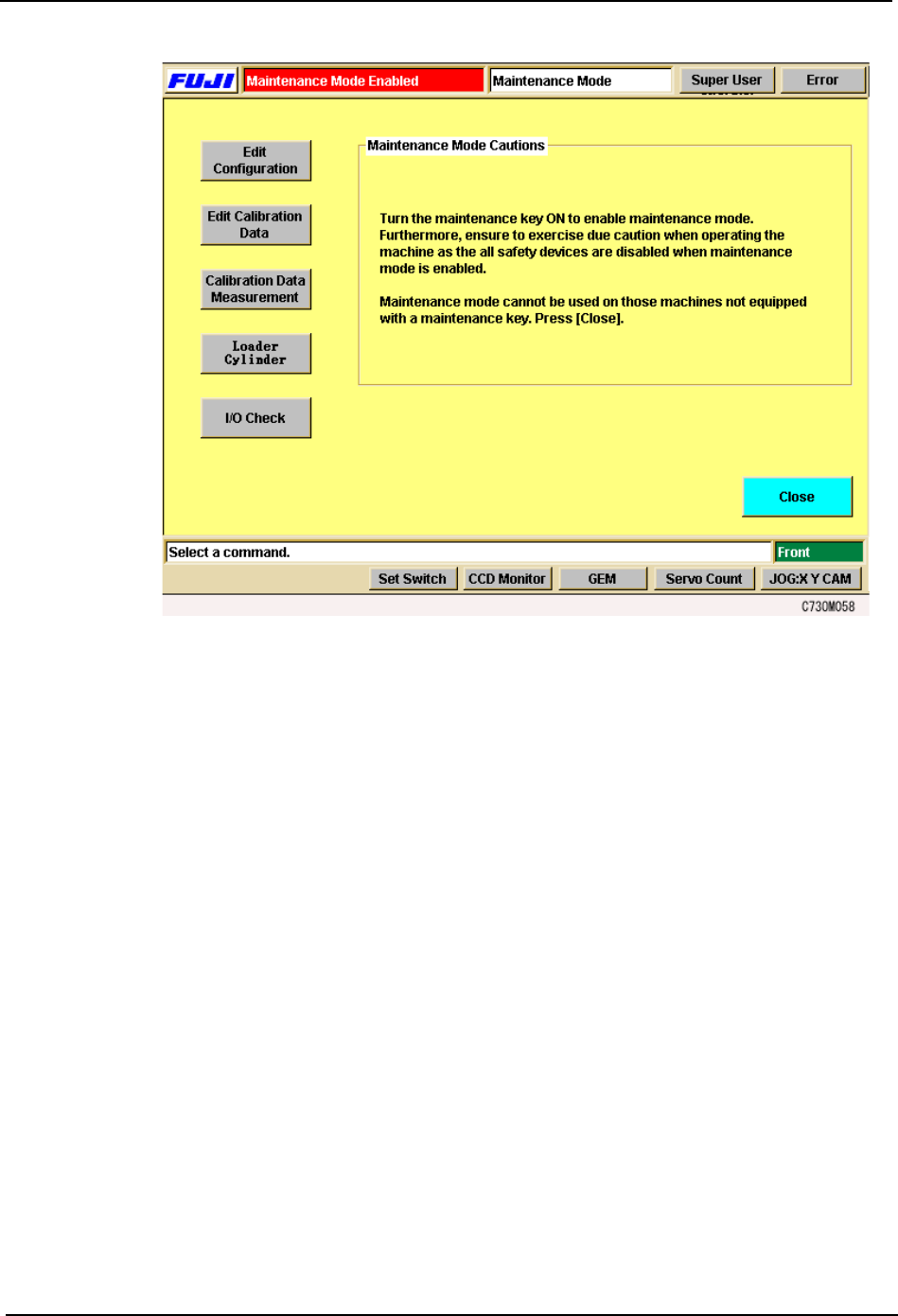
Note: During Maintenance Mode, “Maintenance Mode” displays and flashes in the production program name
area.
3. Select the necessary maintenance operation command from [Edit Configuration], [Edit
Calibration Data], [Calibration Data Measurement], [Loader Cylinder] and [I/O Check]
and perform the adjustment or maintenance.
4. When finished, press the [Close] button and the [Maintenance] screen returns.
3.Machine System SYS-CP842-1.1E
118 CP-842E / CP-842ME System Reference
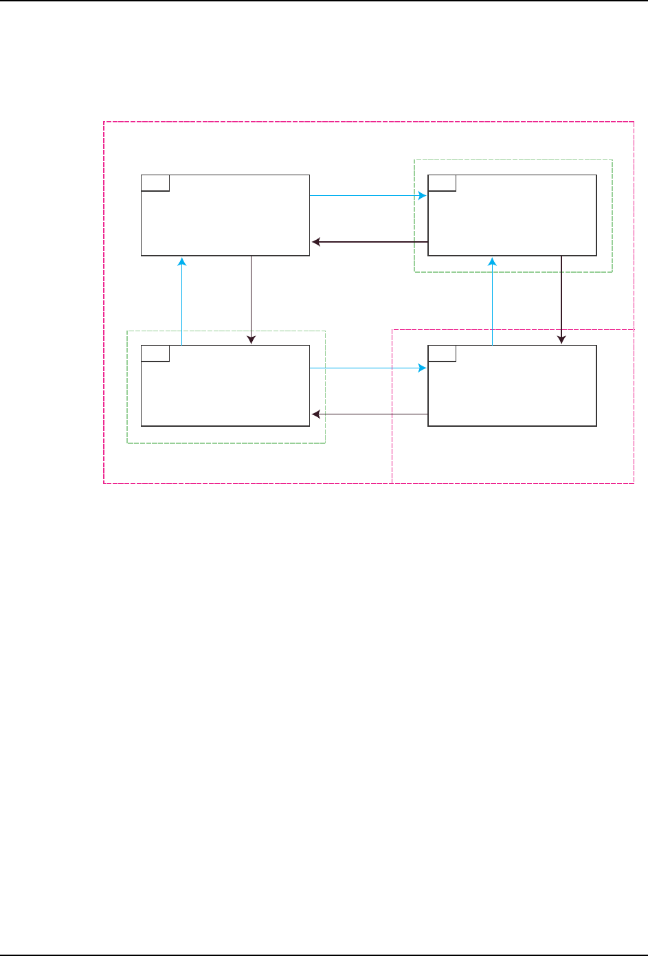
3.4.3 Maintenance Mode Status
Movement between Standard Mode and Maintenance Mode occurs as shown in the figure
below.
1. Standard Mode (Status “1”):
Operation commands other than Maintenance Mode commands are performed. The
Maintenance Key is set to OFF and the [Maintenance Mode] screen is not displayed.
2. The Maintenance key is set to ON but the [Maintenance Mode] screen is not displayed
(Status “2”):
An error occurs. At this stage, the error cannot be cleared. Either move the Maintenance
key to OFF and return to Standard Mode (Status “1”) or clear the error after displaying
the [Maintenance Mode] screen (Status “4”).
3. The [Maintenance Mode] screen is displayed but the Maintenance key is set to OFF
(Status “3”):
An error occurs. At this stage, the error cannot be cleared. Move the Maintenance key
to ON and switch to Maintenance mode (Status “4”) or leave the Maintenance key set
to OFF, close the [Maintenance Mode] screen, return to Standard Mode (Status “1”) and
clear the error.
4. Maintenance Mode (Status “4”)
Maintenance Mode operations can be performed.
1RGTCVKQP2CPGN0QTOCN
/CKPVGPCPEG-G[1HH
1RGTCVKQP2CPGN0QTOCN
/CKPVGPCPEG-G[1P
1RGTCVKQP2CPGN/CKPVGPCPEG/QFG
/CKPVGPCPEG-G[1HH
1RGTCVKQP2CPGN/CKPVGPCPEG/QFG
/CKPVGPCPEG-G[1P
5VCPFCTF/QFG
/CKPVGPCPEG/QFG
'TTQT5VCVWU
'TTQT5VCVWU
/CKPVGPCPEG-G[
1HH
/CKPVGPCPEG-G[
1P
/CKPVGPCPEG-G[
1HH
/CKPVGPCPEG-G[
1P
/CKPVGPCPEG/QFG5ETGGP
1RGP
/CKPVGPCPEG/QFG5ETGGP
%NQUG
/CKPVGPCPEG/QFG5ETGGP
1RGP
/CKPVGPCPEG/QFG5ETGGP
%NQUG
%1/
SYS-CP842-1.1E 3.Machine System
CP-842E / CP-842ME System Reference 119
3.5 Panel ID Read Function (Option)
This manual describes the panel ID reading function, and explains how to use this function.
3.5.1 Function Explanation
This function assigns a unique ID to each panel (or board) for the purpose of traceability.
Panels are identified with either 2D codes or barcodes.
The fiducial mark camera reads 2D codes, and a barcode reader mounted on the in-
conveyor reads barcodes.
Note, however, that not all versions of the machine control software are compatible with the
panel ID read function.
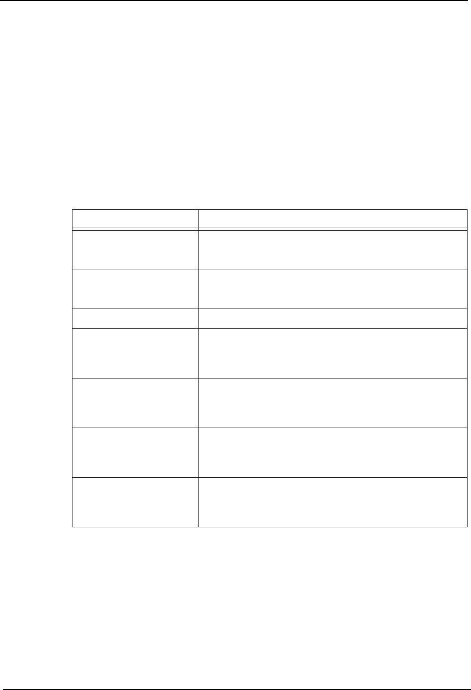
3.5.2 Glossary of Terms
Term Explanation
Verification This function checks the part type on the device table
against the recipe to ensure that the correct part type is
being used.
Device check This refers to the entire check sequence (including
Verification of each device) which is performed to verify that
the devices are ready for production.
FIDL Feeder ID number.
DID Whereas the device comment indicates the part type,
theDID indicates the ID number of each parts reel. Even if
two reels contain the same part types (=device comments),
each reel must have a different DID.
Panel ID When multiple boards are contained within a single panel,
or when multiple boards are conveyed on a single pallet, a
unique Board ID is assigned to each of the individual boards
on the panel or the pallet.
Dedicated barcode reader This is the dedicated panel ID barcode reading sensor
mounted on the in-conveyor. The term “dedicated” is used
because this reader is not used together with the mark
camera. It is also referred to as the “fixed barcode sensor”.
Reading trigger sensor This sensor is used to trigger the panel ID reading by the
barcode reader. Reading occurs when the panel on the in-
conveyor passes beneath this sensor. This sensor is also
referred to as the “fixed panel check sensor”.