SYS-CP842-1.1E.pdf - 第89页
3.Machine System SYS-CP842-1.1E 80 CP-842E / CP-842ME System Reference Display Item Explanations Operation Explanation 1. Start a. The START button lamp bli nks except at th e times shown be low. Simulation begins when t…
SYS-CP842-1.1E 3.Machine System
CP-842E / CP-842ME System Reference 79
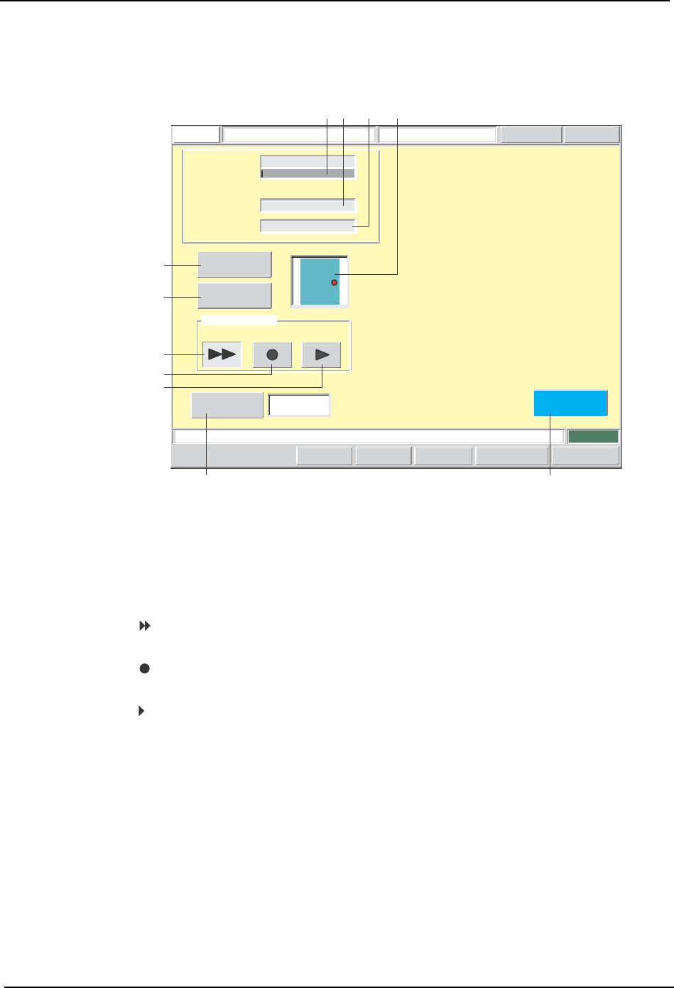
Simulation Screen
Simulations are performed from this screen.
Screen Button Explanations
Load a board, and then press START to commence simulation.
FUJI
ErrorOperator
JOG:X Y CAM
Servo CountGEM
CCD Monitor
SimulationFUJI_CP7_2001
Front
Close
Sequence (%) :
0
Sequence
Number :
Device Number :
1-0-1-0
123
Operation Mode
Continuous Step
Interval Timer
Starting
Sequence
Program Editor
[sec]
1
Set Switch
CP7S2008E
A
B
C
D
E
F G
1
23
4
A. [Production Start Sequence No.]: Switches to the sequence search screen.
B. [Production Program Edit]: Switches to the production program editing
screen.
C. [ ]:
Specifies a simulation in the continuous
operation mode.
D. [ ]:
Specifies a simulation in the step operation’s
repeat mode.
E. [ ]:
Specifies a simulation in the step operation’s 1-
sequence feed mode.
F. [Interval Timer]: Sets the length of intervals between sequences
for simulation in the continuous operation mode.
G. [Close]: Returns to the program switching screen. A
dialog box displays at this time inquiring if the
production program is to be saved. When
saved, production program overwriting occurs.

3.Machine System SYS-CP842-1.1E
80 CP-842E / CP-842ME System Reference
Display Item Explanations
Operation Explanation
1. Start
a. The START button lamp blinks except at the times shown below. Simulation begins
when the blinking START button is pressed.
• When at the sequence screen.
• When editing data (a ten-key pad or an input dialog box displays).
b. Screen buttons are disabled during a simulation.
2. Continuous operation
a. Intervals are inserted between each sequence. The interval length is set at the
simulation screen.
b. Operation continues until all sequences in the production program are completed. If
the CYCLE STOP button is pressed while operation is in progress, a stop does not
occur until the current sequence is completed.
3. Step operation
a. If started when there is no panel present, the initial F-mark reading sequence for
panel loading is performed, and operation then stops.
b. If the [ ] button is pressed, the same sequence is repeated.
c. If the [ ] button is pressed, processing proceeds 1 sequence at a time.
4. Specifying the initial sequence
a. The initial sequence can be specified at all times.
5. Saving the production program
a. When the [Close] button is clicked after editing a production program, a dialog box
displays inquiring if the production program is to be saved. If saved, production
program overwriting occurs. If not saved, the edited content is abandoned.
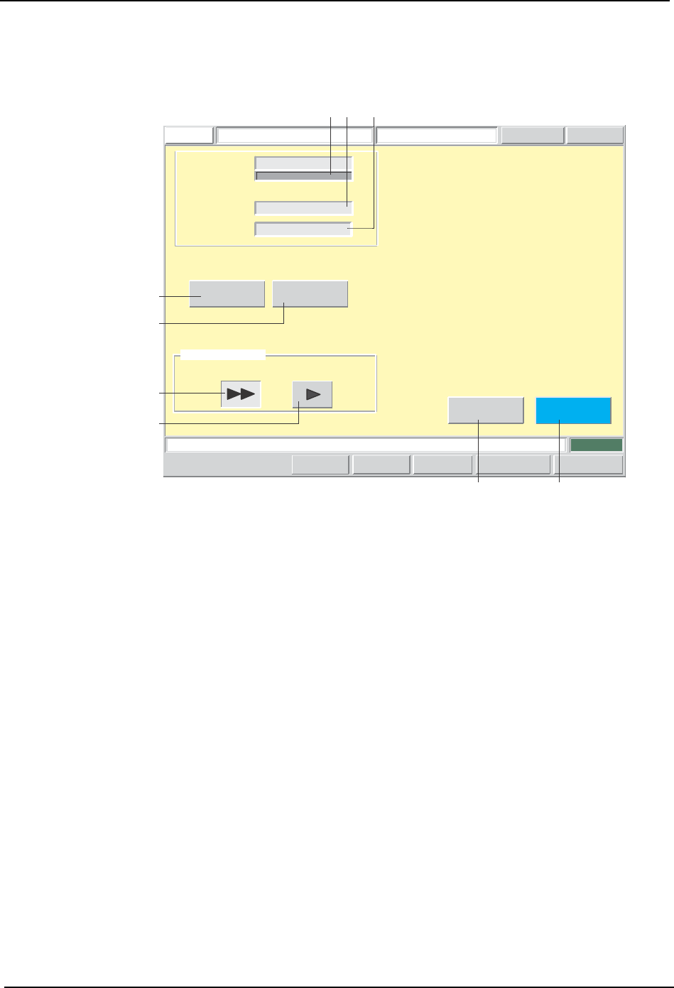
1. [Sequence]: Displays the sequence progression status as a bar graph
which indicates the percentage (%).
2. [Sequence No.]: Displays the sequence number for which image acquisition
(by mark camera) is occurring.
3. [Device No.]: Displays the stage number, group number, slot number, and
sub-slot number of the device for the displayed [Sequence
No.] (see item 2 above).
4. [Monitoring Preview]: Displays the panel position of the sequence for which image
acquisition (by mark camera) is occurring.
SYS-CP842-1.1E 3.Machine System
CP-842E / CP-842ME System Reference 81
Test Placement Panel
Test placement is performed from this screen.
Load a board, and then press START to commence a test run.
FUJI
ErrorOperator
JOG:X Y CAM
Servo CountGEMCCD Monitor
TestFUJI_CP7_2001
Front
Close
Production
Editior
Starting
Sequence
Operation Mode
Sequence (%) :
0
Sequence
Number :
Device Number :
1-0-1-0
123
Continuous Step
Unload
Set Switch
B
A
C
D
EF
12
3
CP7S2009E