SYS-CP842-1.1E.pdf - 第36页
SYS-CP842-1.1E 2.The Machine CP-842E / CP-842ME System Reference 27 to the [Main] scree n. Information ba r g. Messages display in this area of the info rmation bar relating to the main proce dures associated with the sc…
2.The Machine SYS-CP842-1.1E
26 CP-842E / CP-842ME System Reference
2.1.5 Touch Screen
The operator issues commands to the machine from the touch screen at the front or rear of
the machine. Each screen that appears at the touch screen contains a number of command
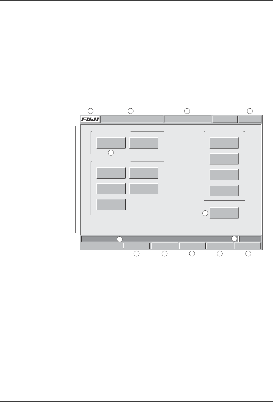
buttons, which display the commands associated with the selection. Some screens, as in
the example below, are divided into sections with related commands being grouped
together.
Although different commands display at each screen, the title bar, information bar, and
command bar commands which are common to all screens (sections A to M in the figure
below) are explained below. Refer to part 3 of this manual for a detailed explanation of the
command hierarchy.
Title bar
a. Press the [FUJI] button to display version information for the machine control
software, vision system software, and operating system.
b. The name of the active program displays at this section of the title bar.
c. The name of the current screen displays at this section of the title bar.
d. This button displays in red if an error occurs. When red, this button can be pressed
at any screen to return to the red error screen.
Main area
e. The command buttons in the main section of each screen can be pressed to access
further related commands. Refer to part 3 for a detailed explanation of the command
hierarchy.
f. The [Close] button is available on all screens except the [Main] screen. Press this
button once to return to the previous screen. Press this button in succession to return
Command section
Screen name
Command section
Select a command.
Command section
COMMAND COMMAND COMMAND
COMMAND
COMMAND
COMMAND
Close
COMMAND COMMAND
COMMAND COMMAND
COMMAND
FRONT
Vision
0
Host Servo Count
Operator CallABC_PROG Error
JOG:XY CAM
Title bar
Main area
Infomation bar
Command bar
C73OM008a
a b cd
e
f
g
h
i
j
k lm
Set Switch

SYS-CP842-1.1E 2.The Machine
CP-842E / CP-842ME System Reference 27
to the [Main] screen.
Information bar
g. Messages display in this area of the information bar relating to the main procedures
associated with the screen above.
h. This displays either FRONT or REAR depending on which side of the machine is
currently set as the active side at which commands at the touch screen can be used.
To change the active side it is necessary to move the side selection switch on the
machine to ENABLE.
Command bar
i. Press the [Set Switch] button to display the [Parts Set Switch] screen. This switch is
used in place of the standard hardware switch to confirm that the setting of parts is
complete.
j. Press the [Vision] button to display a screen at which one of the three cameras can
be selected. When a camera button is pressed the raw image acquired by that
camera displays on screen.
k. Press the [Host] button to display a screen at which the communication and control
status can be specified.
l. Press [Servo Count] to display the [Servo Count] screen. This displays readings in
mm/deg. or pulses for each of the eleven axes on the machine.
m. Press [Jog:] to display a screen at which inching speed and other settings can be
made. The button carries the name of the selected axis combination which will move
when the inching controls are used.

2.The Machine SYS-CP842-1.1E
28 CP-842E / CP-842ME System Reference
2.2 Glossary
This chapter defines some of the terms used throughout this manual. Users familiar with
other Fuji machines should be aware that certain terms may carry different meanings to
those used in other Fuji documentation.
Note: A number of important changes have been made to Fuji terminology which may cause confusion for
users of other Fuji machines. These changes have been made after consulting our users in reference
to applying terminology in alignment with SEMI standards.
What was called a board in the past is now referred to as panel and what was called a block in the past
is now referred to as a board. Therefore, mulitblock board is now called a multiboard panel.
Although recipe is used in the host system FujiCam, production program will continue to be used at the
machine, and in machine related documentation.
advance pick-up
To increase throughput, parts are be picked up in advance during the loading of panels.
board
A board is one of several identical circuits that constitute a panel, which are separated when
assembly is complete.
device (feeder) pallet (CP-842ME Option)
Feeders are loaded on this pallet in order to supply parts.
global skip mark
A mark applied to a multiboard panel to indicate that a skip mark has been attached, and
that the machine must inspect to determine which blocks will be skipped. If a global skip
mark is not detected, parts are placed on the boards on the panel without performing further
skip mark reading. See also multiboard panel.
inching
The action of manually moving a machine axis using the inching keys at the machine. The
inching keys are held down to move the axis to the desired position.
in/out lifter
The metal plates on the inside of the in- and out-conveyor which raise the panel(s) for
clamping on the in-/out-carrier.
in-/out-carrier
The two mechanisms at the in- and out-conveyor, which carry the panel(s) to and from the
XY-table.
machine configuration data
Data that is used specifically for machine settings that vary depending on requirements.
Configuration data allows the operator to change the display at the signal tower, and to
specify the use of functions such as nozzle statictical processing and automatic pick-up
offset. Machine configuration data and calibration data are collectively referred to as
machine data, which is called Proper data for machines other than those in the PCC group
(refer to section 1.2, Whats New About the Machine System). See also calibration data.
multiboard panel
A panel that is composed of several identical smaller boards which are separated when