SYS-CP842-1.1E.pdf - 第63页
3.Machine System SYS-CP842-1.1E 54 CP-842E / CP-842ME System Reference 3. Press [Close] to enter the settings and retu rn to the [Basic Configuration] screen.
SYS-CP842-1.1E 3.Machine System
CP-842E / CP-842ME System Reference 53
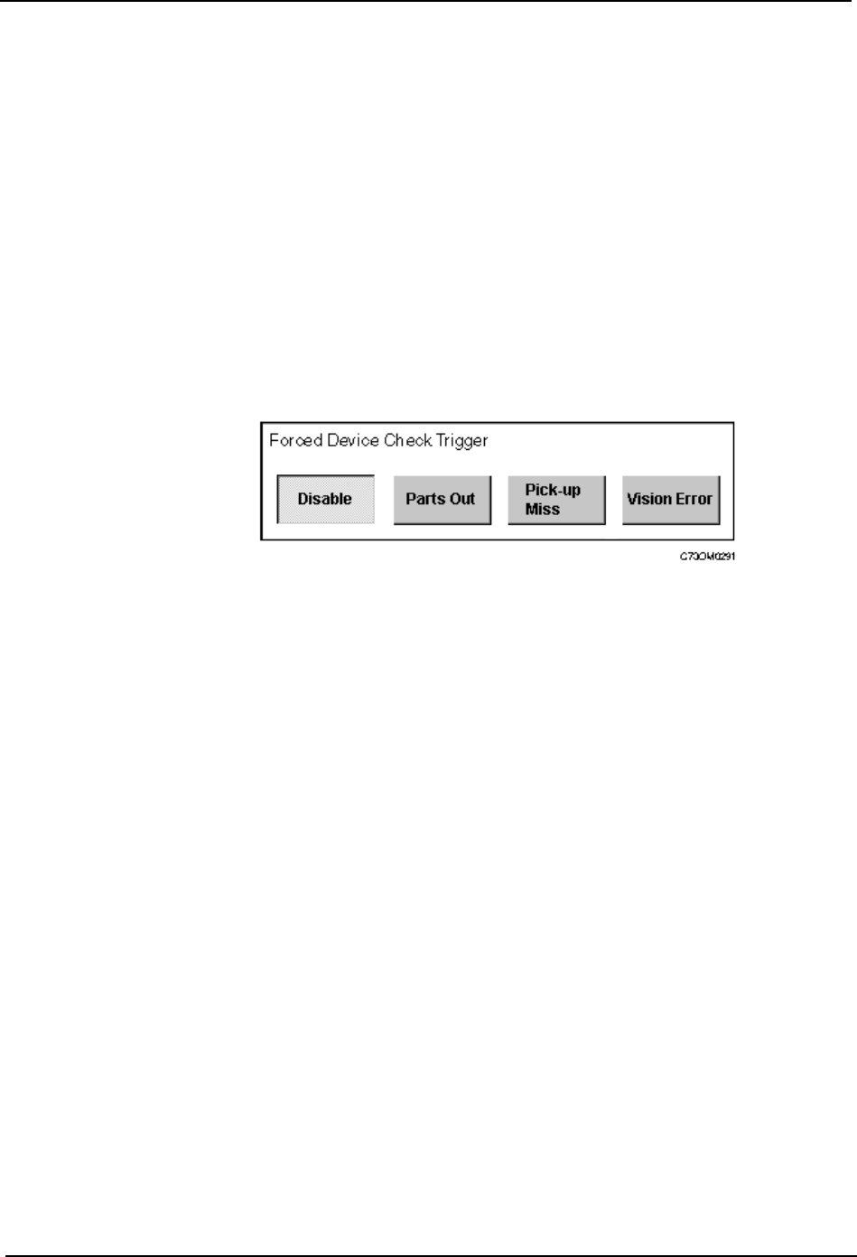
buttons are displayed in the Forced Device Check Trigger section. The followings are
explanations of each button.
2. Under Forced Device Check Trigger, select the event which will invoke an automatic
device check.
3. Press [Close] to enter the settings and return to the [Basic Configuration] screen.
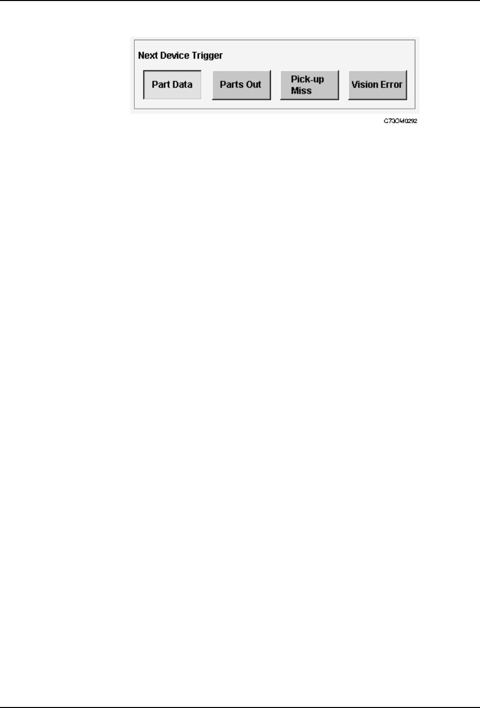
Specifying the Next Device Trigger
Next devices provide a backup for parts supply, allowing the machine to switch to a fresh
feeder loaded with the same parts, when parts run out. The settings for a next device loop
(starting and ending at one feeder), are made in the production program. Refer to your host
system documentation for details of how to specify a next device loop. The type of event
during assembly which causes the machine to switch from one feeder to the next can be
set at the machine. The following settings are available.
The above setting is also applied to the device change mode when switching from the
original table to the spare table.
Procedure
1. Press [Maintenance] at the [Main] screen, and then press [Configuration] - [Basic
Configuration].
2. Under Next Device Trigger, select the event which will cause the machine to switch to
the next device.
None Automatic operation can be entered even when a device check has not
been performed.
Parts Out The [Device Check] screen displays automatically if a parts out error is
detected.
Pick-up Miss The [Device Check] screen displays automatically if a pick-up or parts
out error is detected.
Vision Error The [Device Check] screen displays automatically if a pick-up error,
inspection error, or parts out error is detected.
Part Data The trigger setting in part data is used.Refer to your host system
documentation for details of how to make this setting.
Parts Out The machine switches to the next device when parts out is detected.
Pick-up Miss The machine switches to the next device if a pick-up or parts out error is
detected.
Vision Error The machine switches to the next device if a pick-up error, inspection
error, or parts out error is detected.
3.Machine System SYS-CP842-1.1E
54 CP-842E / CP-842ME System Reference
3. Press [Close] to enter the settings and return to the [Basic Configuration] screen.
SYS-CP842-1.1E 3.Machine System
CP-842E / CP-842ME System Reference 55
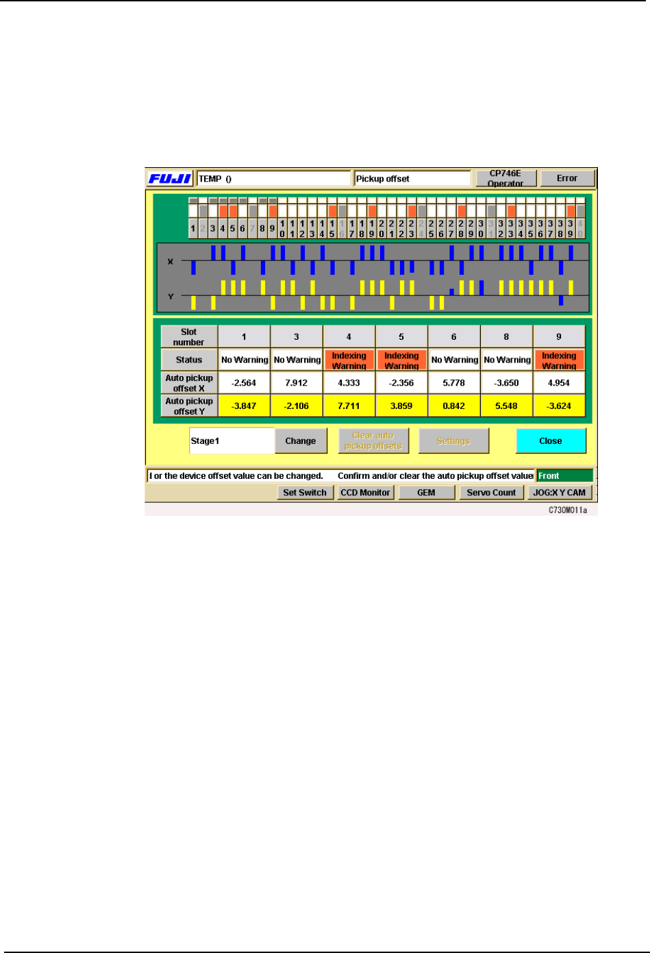
Specifying Pick-up Offsets at the Machine
When a part cannot be successfully picked up using standard pick-up position offsets, the
operator can manually specify the offset at the machine.
Procedure
1. Press [Device Offsets] at the [Main] screen. The [Device Offsets] screen displays.
2. The XY orientation of the pick up position can be changed on the CP-842E/842ME.
Under each slot number, the slot warning status and X and Y auto pick up offset values
display. Select a slot number on the device table displayed at the top of the screen to
display information for that slot (for CP-842ME, 1 to 40, for CP-842E, 1 to 70). Press
[Change] to toggle the display between Stage 1 and Stage 2.
Note: Y pick up offsets cannot be edited manually.
3. To clear auto pick up offsets, select [Auto pick up offset X] or [Auto pick up offset Y] for
the corresponding slot and push [Clear auto pick up offsets].
4. To manually change the X auto pick up offset values, select the slot number of the slot
to be changed, press [Settings] and the window shown below displays. Push [Change]
and enter the offset values via the numerical pad that displays.