SYS-CP842-1.1E.pdf - 第73页
3.Machine System SYS-CP842-1.1E 64 CP-842E / CP-842ME System Reference Troubleshooting The following table shows the corr ective actions for errors wh ich may occur during automatic c onveyor width ad justments. Next-Sta…

SYS-CP842-1.1E 3.Machine System
CP-842E / CP-842ME System Reference 63
Screen Button Explanations
2. When the [Style] button is pressed, the START button becomes enabled. If the START
button is then pressed, all panels are unloaded from the machine.
Note: When set so that panels are not being transferred to a next stage, the last unloaded panel remains on
the conveyor. In this case, be sure to remove the panel from the conveyor by hand before using inching
or conveyor width change commands.
3. Press the [Panel Width] or [Margin] button to display a numeric keypad, then entire the
desired setting values. The total of the “Panel Width” + “Margin” values displays as the
“Target Width”.
4. The START button is enabled when either the [Specified Width] or [Maximum Width]
button is pressed.
5. Press the START button to perform the conveyor width change.
A. [Panel Width]: Specifies the Y-direction size of the production program panel.
B. [Margin]: Specifies the clearance between the conveyor and panel.
C. [Style]: Prepares for a conveyor width change (panel unloading, conveyor rail
linkage, etc.).
D. [Maximum Width]: Adjusts the conveyor to its maximum width minus 1 mm.
E. [Specified Width]: Adjusts the conveyor to the specified width.
F. [Margin Measurement]: Oeasures the margin (clearance between conveyor and
panel).
G. [Close]: Returns to the [Main] screen.
3.Machine System SYS-CP842-1.1E
64 CP-842E / CP-842ME System Reference
Troubleshooting
The following table shows the corrective actions for errors which may occur during
automatic conveyor width adjustments.
Next-Stage Follow-Up Control
CP-842E/842ME do not support follow-up control related to conveyor width changes. For
example, if a conveyor width change is performed at the previous stage machine in the line,
the operator must perform the same conveyor width change on the CP-842E/842ME.
CP-842E/842ME do not support follow-up control related to conveyor width changes. For
example, if a conveyor width change is performed at the previous stage machine in the line,
the operator must perform the same conveyor width change on the CP-842E/842ME.
On the other hand, if the next stage machine supports follow-up control related to conveyor
width changes, this follow-up control can be enabled by adding a follow-up dog to the CP-
842E/842ME.
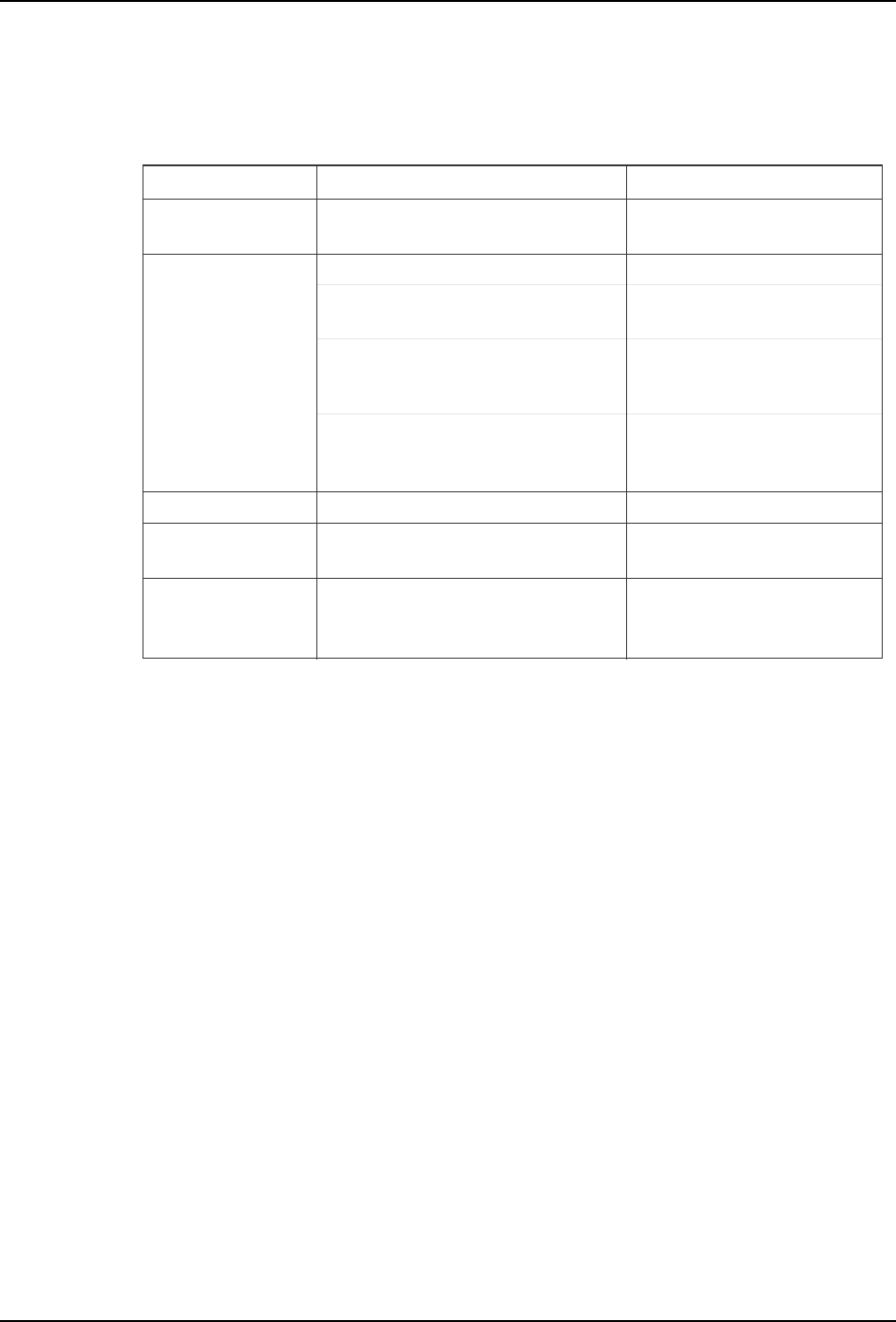
Error Cause Corrective Action
T011E
Internal error in the conveyor
width change shell
"Panel check" error
during automatic
conveyor width change
Operation error
Backup pin detection
Conveyor control board failure at start-up,
etc.
Conveyor motion interference. Remove the obstacle.
Backup pins were detected. Remove the backup pins.
Cover is open
The cover at the previous or next stage
machine is open.
Close the cover at the previous or
next stage machine.
Backup pin detection problem.
Press the EMERGENCY STOP
button, then remove the backup pins.
Software limit was reached during operation.
Perform inching to bring the
conveyor width back within its
prescribed motion range.
A [Maximum Width] or [Specified Width]
command was executed when the conveyor
width was outside the software limits.
Perform inching to bring the
conveyor width back within the
software limits.
The "panel check" sensor detected the
presence of a panel in the loader during
a conveyor width change.
Remove the panel from the loader,
or check the sensor.
Perform a "data trace" operation,
then contact your Fuji representative.
SYS-CP842-1.1E 3.Machine System
CP-842E / CP-842ME System Reference 65
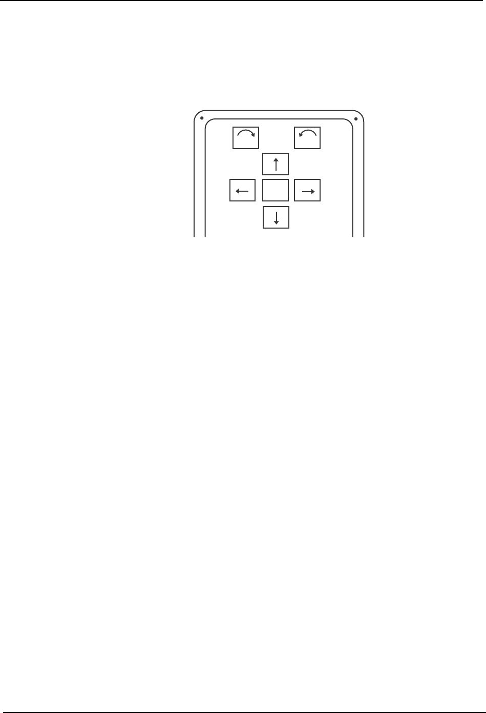
3.1.12 Inching
Moving an Axis With the Inching Keys
Inching is performed using the inching keys on the operation console. Inching can be
performed at any time except under the following conditions:
• When the machine is in START ready status
• During operation
• Before the cause of an emergency stop has been cleared
• When displaying the I/O command page
To inch an axis, press the inching key corresponding to the target axis and direction.
To move the target axis faster, hold down F (fast) as well as the chosen inching key for rapid
inching.
The axis combination displays at the [JOG] button in the command bar of the touch screen.
F
θ
θ
C7SS2001