SYS-CP842-1.1E.pdf - 第28页
SYS-CP842-1.1E 2.The Machine CP-842E / CP-842ME System Reference 19 3. Advance pick-up The machine picks up parts in ad vance, while the panel is tran sferred from th e in-c onveyor to the in-c arrier (C). 4. Mark read i…
2.The Machine SYS-CP842-1.1E
18 CP-842E / CP-842ME System Reference
By using a standard PC system, many features common to PC environments are now part
of Fuji’s machines.
• Software upgrades delivered on CD-ROM.
• Ethernet networkability.
• Storage of data on hard disk.
• Incorporation of functions such as the vision system and SECS/GEM protocol, as
software running on the main system.
2.1.3 Machine Movement During Operation
The explanation below provides a description of machine movement from the point a panel
is loaded onto the in-conveyor to the point where the panel is unloaded from the out-
conveyor.
1. Panel check
When the START button is pressed, a check is made of whether a panel is present on the
conveyor.
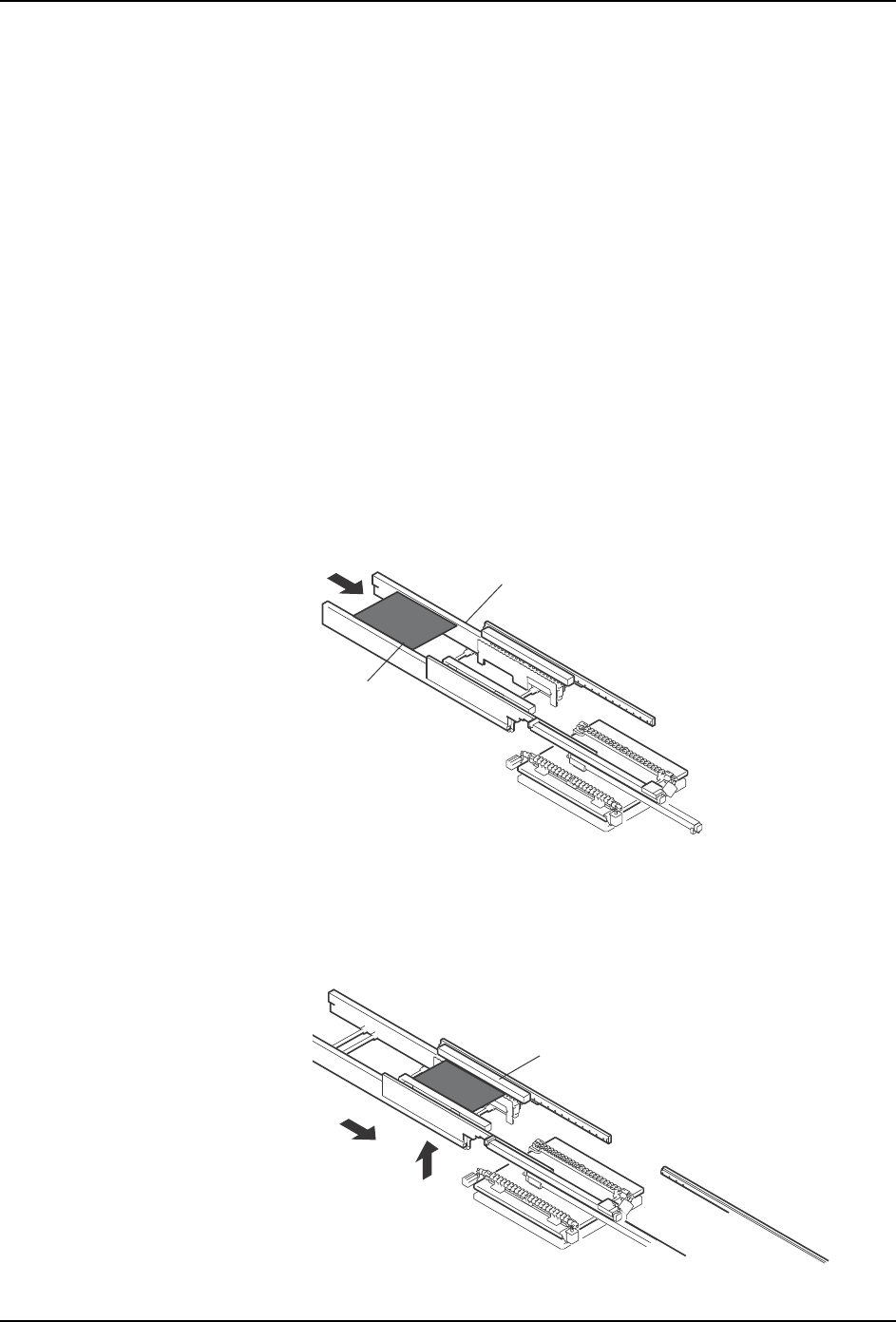
2. Panel loading
A panel is loaded onto the in-conveyor (A).
The loaded panel is then lifted and transferred to the in-carrier (B).
A
In-conveyor
Panel
B
In-carrier
SYS-CP842-1.1E 2.The Machine
CP-842E / CP-842ME System Reference 19
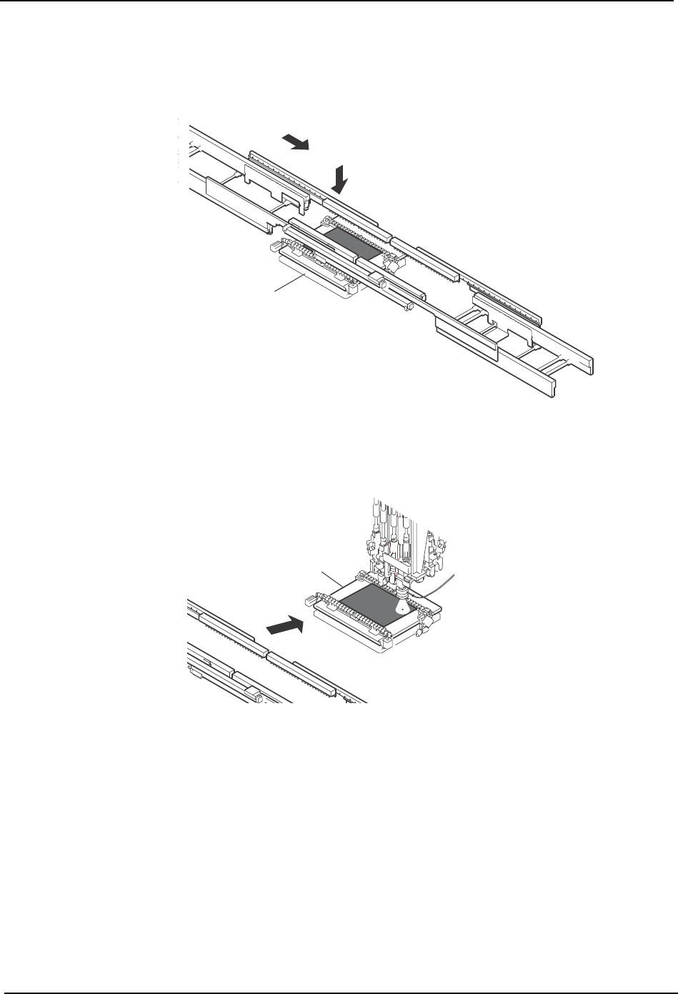
3. Advance pick-up
The machine picks up parts in advance, while the panel is transferred from the in-conveyor
to the in-carrier (C).
4. Mark reading
After the panel has been loaded onto the XY-table, the fiducial marks are read (D).
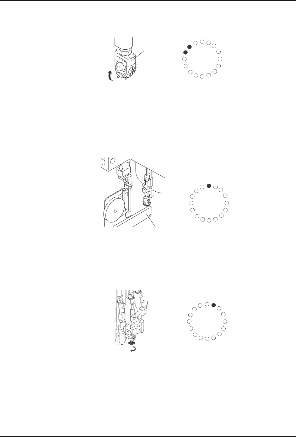
5. Nozzle change
A nozzle check is performed at Station 15 to establish which nozzle is currently down. If a
different nozzle is required for pick-up, the rotary head is indexed at station 14 until the
required nozzle is in position.
Another check is performed at Station 15 to confirm that the correct nozzle is currently down
(E).
C
XY-table
D
G
o
to
&
W
illia
m'
s
L
a
b
o
r
a
t
r
ie
s
XY-table
C7SM1001a
2.The Machine SYS-CP842-1.1E
20 CP-842E / CP-842ME System Reference
6. Pick-up
When the selected nozzle reaches Station 1, the cam speed is adjusted and the nozzle
lowers to the pick-up position, stops and picks up the part. If pick up offsets in the Y direction
are necessary, the NY-axis performs the necessary movements prior to pick up. (F)
7. Pre-rotation
Pre-rotation is performed at station 2 (G).
8. Part inspection
At station 5 the part is inspected by the CCD camera (H).
E
ST1
ST2
ST3
ST4
ST5
ST6
ST7
ST8
ST9
ST13
ST16
ST15
ST14
ST12
ST11
ST10
Nozzle holder
ST1
ST2
ST3
ST4
ST5
ST6
ST7
ST8
ST9
ST13
ST16
ST15
ST14
ST12
ST11
ST10
F
Feeder
ST1
ST2
ST3
ST4
ST5
ST6
ST7
ST8
ST9
ST13
ST16
ST15
ST14
ST12
ST11
ST10
G