SYS-CP842-1.1E.pdf - 第85页
3.Machine System SYS-CP842-1.1E 76 CP-842E / CP-842ME System Reference Test Placement Command Places a part and a cquires an image of the placement position, and displays a wire fra me representation on th e monitor. 4. …

SYS-CP842-1.1E 3.Machine System
CP-842E / CP-842ME System Reference 75
3.2 Editing Production Programs On the Machine
3.2.1 Function Explanation
This function uses the machine’s vision processing function to check for deviations between
the panel pattern or mounted parts, and the data image (wire frame). It also allows mark
data, placement coordinates, and part data to be fine-adjusted on the machine. This
function uses “simulation” and “test placement” commands. The wire frame, and the
“simulation” and “test placement” commands are explained below.
Wire Frame
The wire frame tool provides a visual representation of the mark and part data which is
registered in a production program.
Simulation Command
Acquires an image of the part placement position without the part being placed, and
displays a wire frame representation on the monitor.
1. Fiducial mark sequence
a. The panel’s mark pattern is compared with the wire frame to check for mark pattern
errors.
b. The panel’s mark pattern is compared with the wire frame to check for reading
position deviations.
2. Block skip mark sequence
a. The panel’s mark pattern is compared with the wire frame to check for reading
position deviations.
3. Placement sequence
a. The panel pattern is compared with the wire frame to check for part placement errors.
b. The panel pattern is compared with the wire frame to check for placement position
deviations.
c. The panel pattern is compared with the wire frame to check the part placement angle.
Note: When a placement position image is acquired at a placement sequence, the placement position is
corrected based on the vision processing result from the fiducial mark reading operation.
Fiducial marks: Draws the mark shapes and displays them on the monitor.
Block skip marks: Draws the mark images based on their X,Y sizes, and displays
them on the monitor.
Placement sequence: Draws the part shape and displays it on the monitor.

3.Machine System SYS-CP842-1.1E
76 CP-842E / CP-842ME System Reference
Test Placement Command
Places a part and acquires an image of the placement position, and displays a wire frame
representation on the monitor.
4. Placing sequence
The part is compared with the wire frame to check for feeder setup errors.
The part is compared with the wire frame to check the part supply direction.
3.2.2 Editing Production Programs
The “simulation” and “test placement” commands can be used to locate and edit production
program data errors and coordinate value deviations.
Procedure
The editing procedure steps are explained below.
1. Program check using the simulation command
a. Begin simulation in either the CONTINUOUS or STEP mode.
b. Check the panel pattern and wire frame match.
2. Editing and rechecking the program
a. Proceed to the data editing screen for the sequence to be edited, then edit the data
on the machine.
b. Begin another simulation of the edited sequence. Repeated simulations can be
performed for a sequence which is being edited.
Note: The panel is not unloaded when the simulation is completed.
3. Saving the edited program
a. Click the [Close] button at the simulation command screen to display a “save
production program” dialog box. When saved, production program overwriting
occurs.
4. Program check using the test placement command
a. Begin a test placement in either the CONTINUOUS or STEP mode.
b. Check the placed part and wire frame match.
5. Editing the program
a. Proceed to the data editing screen for the sequence to be edited, then edit the data
on the machine.
b. Execute the test placement command again.
Note:
1.
Another placement cannot be executed using edited data as this will result in a double
placement.
2.The panel is not unloaded when the test placement is completed.
SYS-CP842-1.1E 3.Machine System
CP-842E / CP-842ME System Reference 77
6. Saving the edited program
a. Click the [Close] button at the test placement command screen to display a “save
production program” dialog box. When saved, production program overwriting
occurs.
7. Rechecking the data
a. Execute the simulation command again and verify that the panel parts match the wire
frame.
b. Load a new panel and execute the test placement command again to recheck the
results.
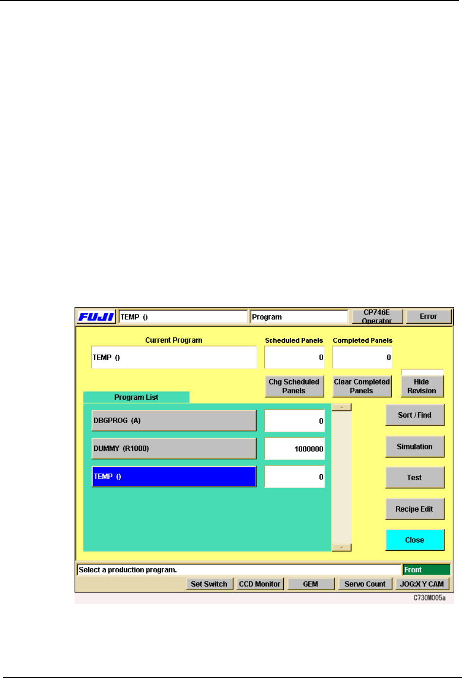
3.2.3 Commands for Editing Production Programs on the Machine
Each of the commands are explained below.
Accessing the Commands for On-Machine Editing
The simulation and test placement commands can be accessed in the following two ways.
1. At the [Production Mode] screen, select either [Simulation] or [Test Placement], then
begin automatic operation by clicking [Auto] at the [Main] screen.
2. At the [Program] screen, click [Simulation] and [Test Placement].