SYS-CP842-1.1E.pdf - 第135页
3.Machine System SYS-CP842-1.1E 126 CP-842E / CP-842ME System Reference sensor which triggers barcode re ading is moved toge ther with th e barcode read er. In some cases, however, changes in the produ ction panel and th…
SYS-CP842-1.1E 3.Machine System
CP-842E / CP-842ME System Reference 125
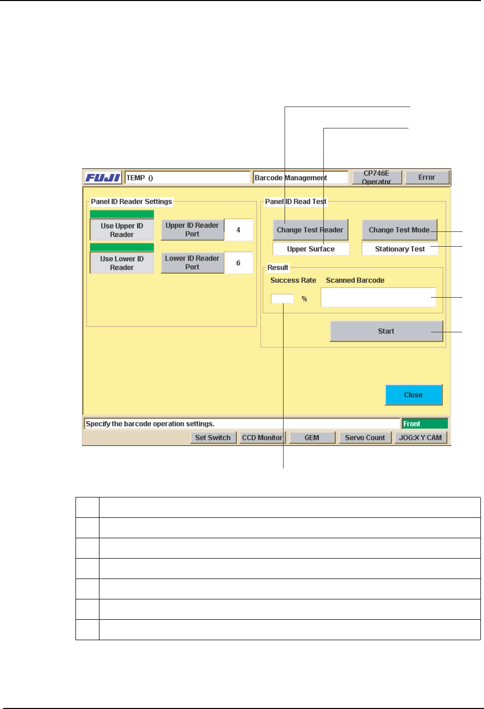
Management] screen and perform a test reading of the panel ID barcode, and fine-adjust
the barcode reader position until the barcode is being read properly.
Place a panel on the conveyor, then press [Test Start or End]. Fine-adjust the reader
position until the reading success rate is high (approx. 100%).
Reading Trigger Sensor Adjustment
When the position of the panel ID changes due to a production panel change, etc., the
9 Selects the reader (upper or lower) to be used for reading test
10 Indicates the reader (upper or lower) being used for reading test.
11 Switches the test mode being used for reading test.
12 Indicates the current test mode being used for reading test.
13 Starts and stops the test.
14 Display area for reading success rate / success count.
15 Display area for content of barcode which was read.
9
10
11
12
13
14
15
%1/
3.Machine System SYS-CP842-1.1E
126 CP-842E / CP-842ME System Reference
sensor which triggers barcode reading is moved together with the barcode reader. In some
cases, however, changes in the production panel and the panel ID position may result in a
panel color or shape which prevents stable detection of the panel edge, and the sensor may
fail to trigger the barcode reading operation.
In such cases, the reading trigger sensor must be adjusted so that reading is triggered in a
stable manner before the panel has moved past the sensor.
Adjust the following as necessary:
• Position (Y-direction)
• Height
In-conveyo
r
Production panel
Barcode reader
Height adjustment
Position (Y-direction) adjustment
Trigger sensor
SYS-CP842-1.1E 4.Commands
CP-842E / CP-842ME System Reference 127
4. Commands
This part contains the command hierarchy and a list of all the commands on the
machine.
4.1 Command Hierarchy
This chapter gives the command hierarchy of the commands on the machine.
The command hierarchy is designed to provide the operator with an easy and under-
standable overview of the commands and their hierarchical relationship.
Each of the machines touch screens contains a number of commands, and these are
represented as a single branch (or vertical line) in the command hierarchy.
The correlation between the commands as they occur at the interface and as they are
represented in the command hierarchy is shown in the figure below.
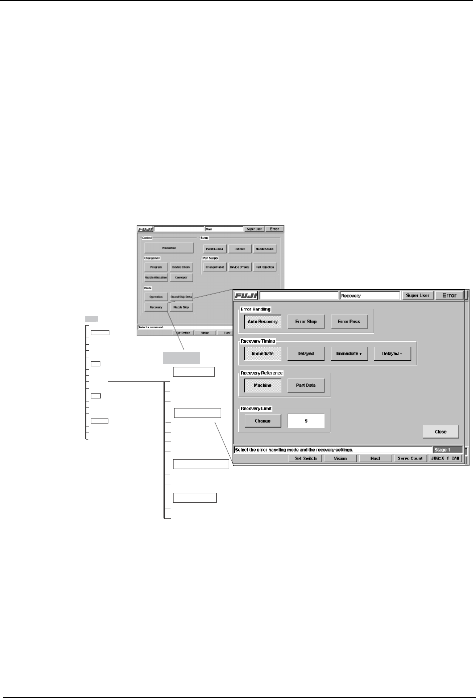
As can be seen, the name of the each screen is given in a shaded box at the top of the
branch. In certain screens commands are positioned in functionality related groups,
which are demarcated on the machine interface by a thin line and a group name.
These section names display in the command hierarchies in clear boxes, e.g., Error
Handling in the example above.
Main
Production
Auto Recovery
Error Stop
Machine
Close
Recovery Reference
Error Handling
Error Pass
Immediate
Recovery Timing
Delayed
Immediate +
Delayed +
Part Data
Change
Recovery Limit
Main
Program
Device Check
Nozzle Allocation
Changeover
Conveyor
Operation
Board Skip Data
Recovery
Mode
Nozzle Skip
Panel Loader
Position
Nozzle Check
Setup
Change Pallet
Device Offsets
Part Rejection
Part Supply
Recovery
CR7SC001a