SYS-CP842-1.1E.pdf - 第116页
SYS-CP842-1.1E 3.Machine System CP-842E / CP-842ME System Reference 107 Element Data Editing Screen Element data can be e dited from this screen . For element da ta deta ils, refer to the SMD3 Operation Manual. Push the …
3.Machine System SYS-CP842-1.1E
106 CP-842E / CP-842ME System Reference
Editing Operations
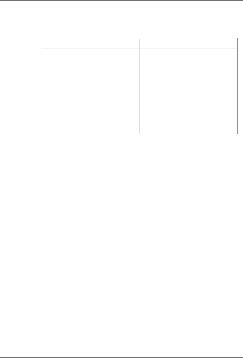
The following editing operations can be performed at this screen.
Problem Editing Operation
A vision processing error occurs during test
placement.
Error code: 0x1CA18005
No part line was found.
Error code: 0x1CA18006
No part line was found.
If the vision type is incorrect, edit the vision
type setting.
A vision processing error occurs during test
placement.
If the lighting is incorrect, edit the lighting
setting.
A vision processing error occurs during test
placement.
Error code: 0x1CB01101
Incorrect camera type setting.
If the camera type is incorrect, edit the
camera type setting.
T007E
SYS-CP842-1.1E 3.Machine System
CP-842E / CP-842ME System Reference 107
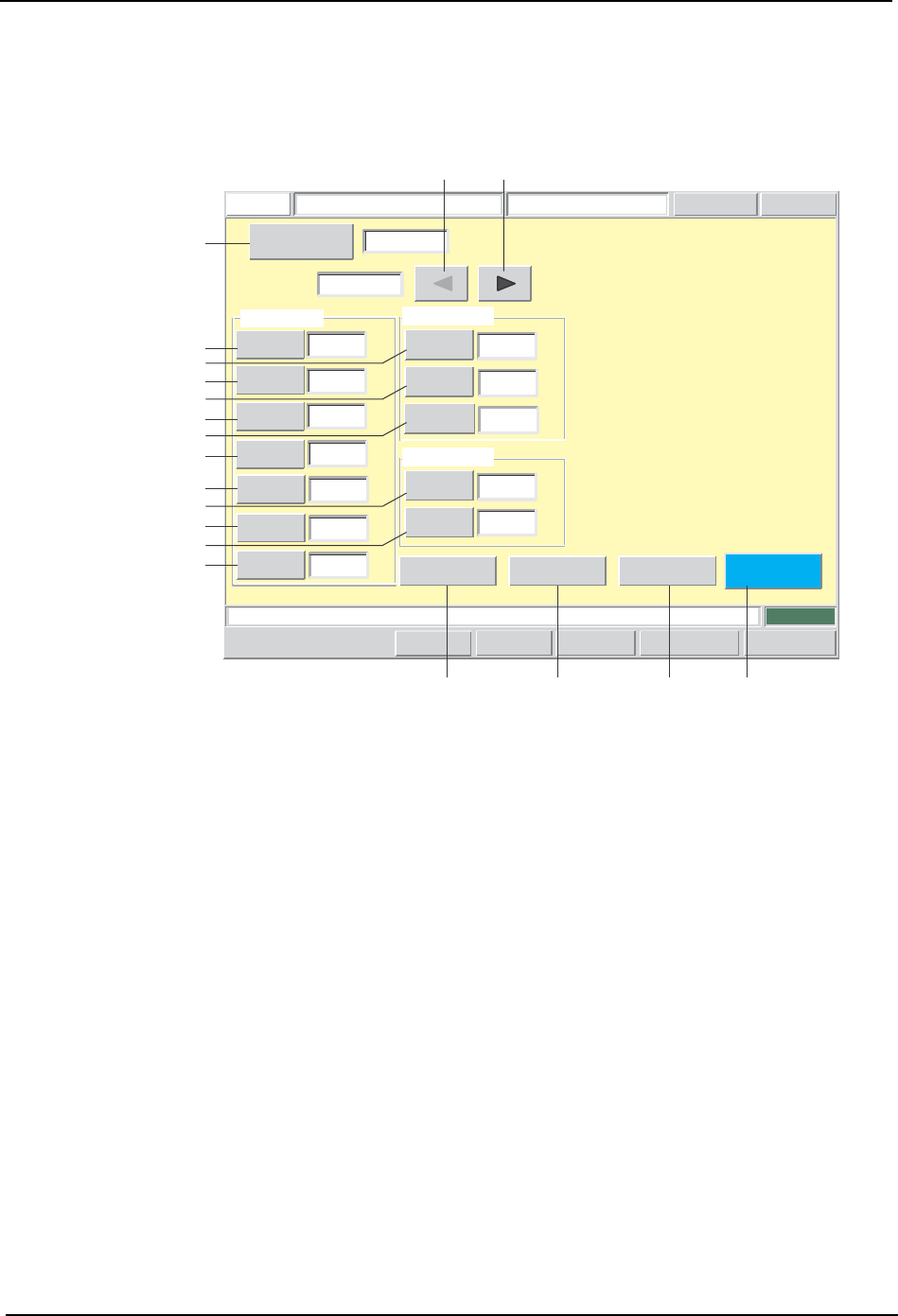
Element Data Editing Screen
Element data can be edited from this screen. For element data details, refer to the SMD3
Operation Manual.
Push the START button.
FUJI
Error
Operator
JOG:X Y CAM
Servo Count
GEMCCD Monitor
Element Data Editor
FUJI_CP7_2001
Front
Close
-0.6200
Position
X
Y
0.0000
[mm]
[mm]
0.1000
Lead Tolerance Values
Length
Width
0.1000
[mm]
[mm]
0.1000
Deviation
[mm]
Lead Data
Side
Number
0
P Pattern
3
Result 1
Pitch
0.0000
Width
0.3000
[mm]
0.5000
Length
[mm]
Count
1
[mm]
Lead
Body
Vision
Type
123
Sequence Number
1
Element
Set Switch
CP7S2020E
A
D
E
F
G
H
I
J
SRQP
B C
K
L
M
N
O

3.Machine System SYS-CP842-1.1E
108 CP-842E / CP-842ME System Reference
Screen Button Explanations
A. [Sequence No.]: Switches to the sequence search screen.
B. [ ]:
Changes the element data item which is being
edited. If element number 1 is being edited, the
item is disabled (grayed out) when this button is
clicked.
C. [ ]:
Changes the element data item which is being
edited. If final element number is being edited, the
item is disabled (grayed out) when this button is
clicked.
D. [Length]: Changes the lead element length (PGDELL) which
is specified in the production program’s part shape
data (ELDT).
E. [Width]: Changes the lead element width (PGDELW) which
is specified in the production program’s part shape
data (ELDT).
F. [Pitch]: Changes the lead element pitch (PGDELP) which
is specified in the production program’s part shape
data (ELDT).
G. [Number of Leads]: Changes the number of lead element leads
(PGDELQ) which is specified in the production
program’s part shape data (ELDT).
H. [Side No.]: Changes the lead element position (direction)
(PGDELSN) which is specified in the production
program’s part shape data (ELDT).
I. [P-Pattern]: Changes the lead element’s lead display pattern
(PGDELPP) which is specified in the production
program’s part shape data (ELDT).
J. [Result]: Changes the lead element’s check content
(PGDELR) which is specified in the production
program’s part shape data (ELDT).
K. [Length] (Lead tolerance): Changes the lead element’s lead length tolerance
(PGDELLT) which is specified in the production
program’s part shape data (ELDT).
L. [Width] (Lead tolerance): Changes the lead element’s lead width tolerance
(PGDELWT) which is specified in the production
program’s part shape data (ELDT).
M. [Deviation] (Lead tolerance): Changes the lead element’s lead bend tolerance
(PGDELCT) which is specified in the production
program’s part shape data (ELDT).
N. [X] (Position): Changes the lead element position’s X-coordinate
(PGDELX) which is specified in the production
program’s part shape data (ELDT).
O. [Y] (Position): Changes the lead element position’s Y-coordinate
(PGDELY) which is specified in the production
program’s part shape data (ELDT).
P. [Vision Type]: Switches to the vision type editing screen.