SYS-CP842-1.1E.pdf - 第23页
1.Safety Guideline SYS-CP842-1.1E 14 CP-842E / CP-842ME System Reference 1.6 Locking System When performing maintenance or service on th e machine, all personnel who service the machine should us e locks to prevent other…
SYS-CP842-1.1E 1.Safety Guideline
CP-842E / CP-842ME System Reference 13
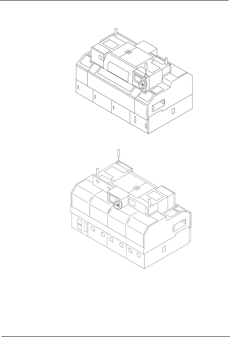
1.5.2 <CP-842ME>
C7SM0009
Front side
Rear side
1.Safety Guideline SYS-CP842-1.1E
14 CP-842E / CP-842ME System Reference
1.6 Locking System
When performing maintenance or service on the machine, all personnel who service the
machine should use locks to prevent others from turning on the machine power or air. This
procedure is referred to as a lockout.
To prevent accidents, especially those caused by mistakes when multiple operators are
present, all related personnel should have thorough knowledge of lockout procedures.
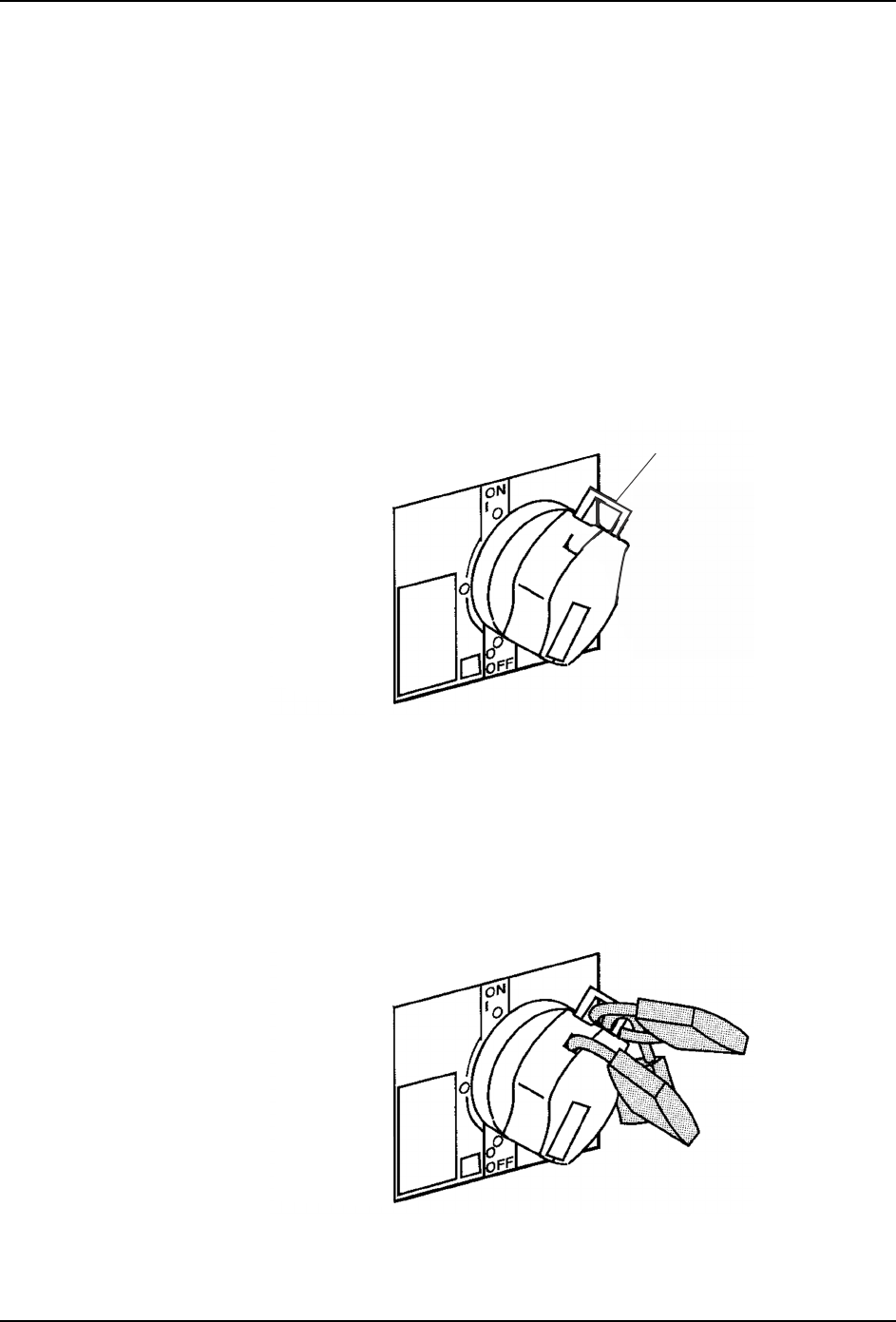
1.6.1 Lockout Procedure
Prepare commercially available padlocks (5-8mm diameter shackle for the main switch),
and require all service personnel to carry lockout nametags.
1. Shut down the machine.
2. Rotate the main switch to the OFF position and pull out the lever.
3. Lock the main switch with a padlock. Use at least one padlock, and more if possible,
depending on the diameter of the lock shackle. Three padlocks are used in the diagram
below. All personnel who will work on the machine should attach their lockout nametags
to the padlock.
Note: The presence of a nametag on the padlock signals that the machine is being serviced and that the lock
is not to be removed.
4. In the same manner, rotate the air valve handle to the OFF position and lock with a
padlock. All personnel who will work on the machine should attach their lockout
Lever
C8SM0001
C8SM0002
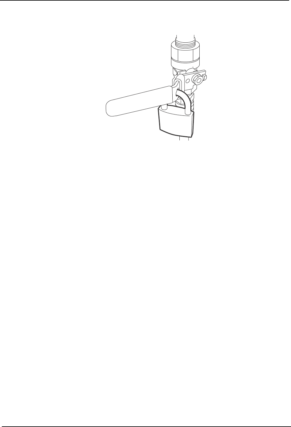
SYS-CP842-1.1E 1.Safety Guideline
CP-842E / CP-842ME System Reference 15
nametags to the padlock.
5. The lockout is complete.
NXTSAF005