FlexTRAK 2MB Material Handler Addendum Rev 05.pdf - 第109页
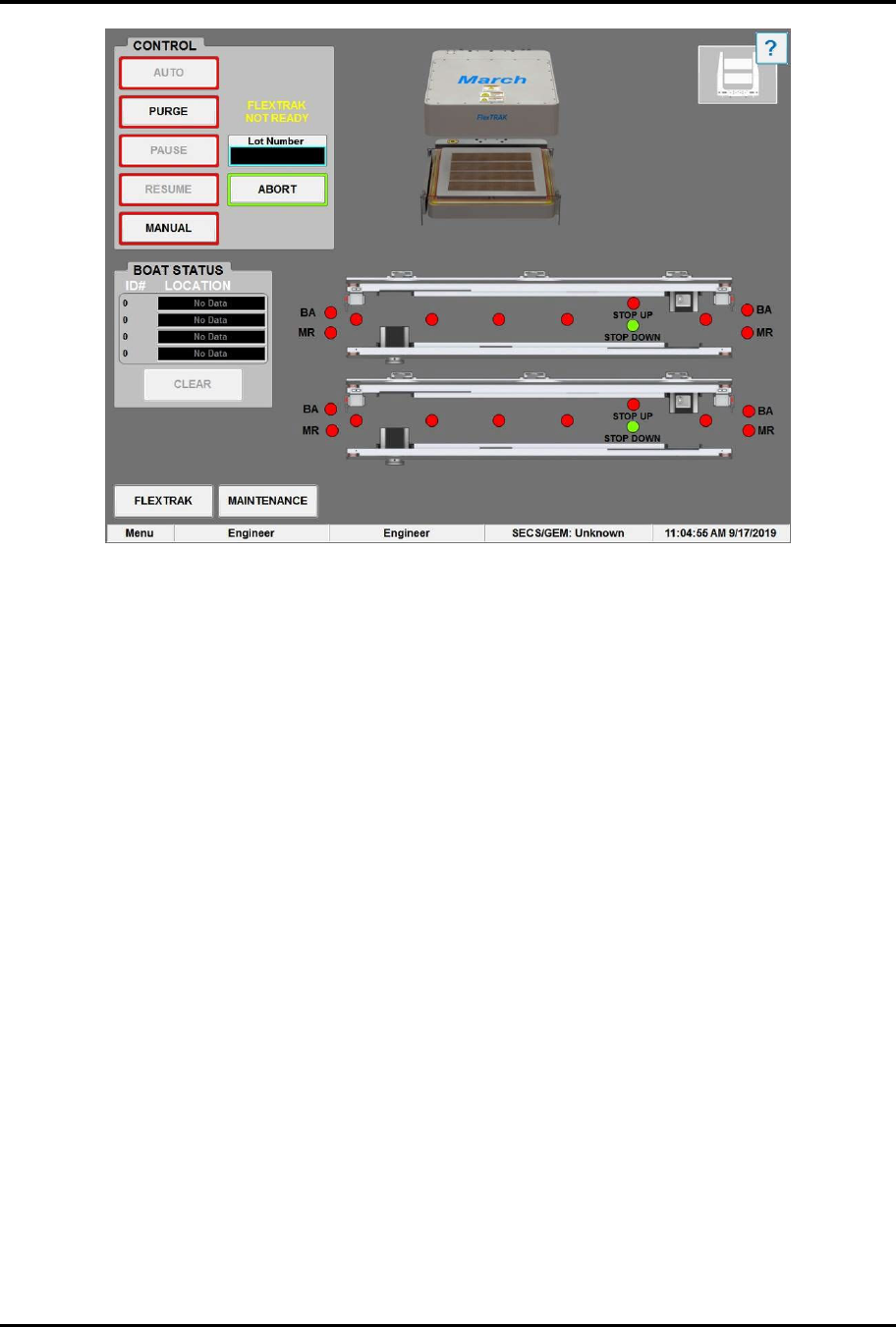
FlexTRAK Series 2MB Mater ial Handler Adden dum Operations © 2023 Nordson Corporation 6-5 Figure 6-5 MH Overview Screen - Log ged On
FlexTRAK Series 2MB Material Handler Addendum Operations
6-4 © 2023 Nordson Corporation
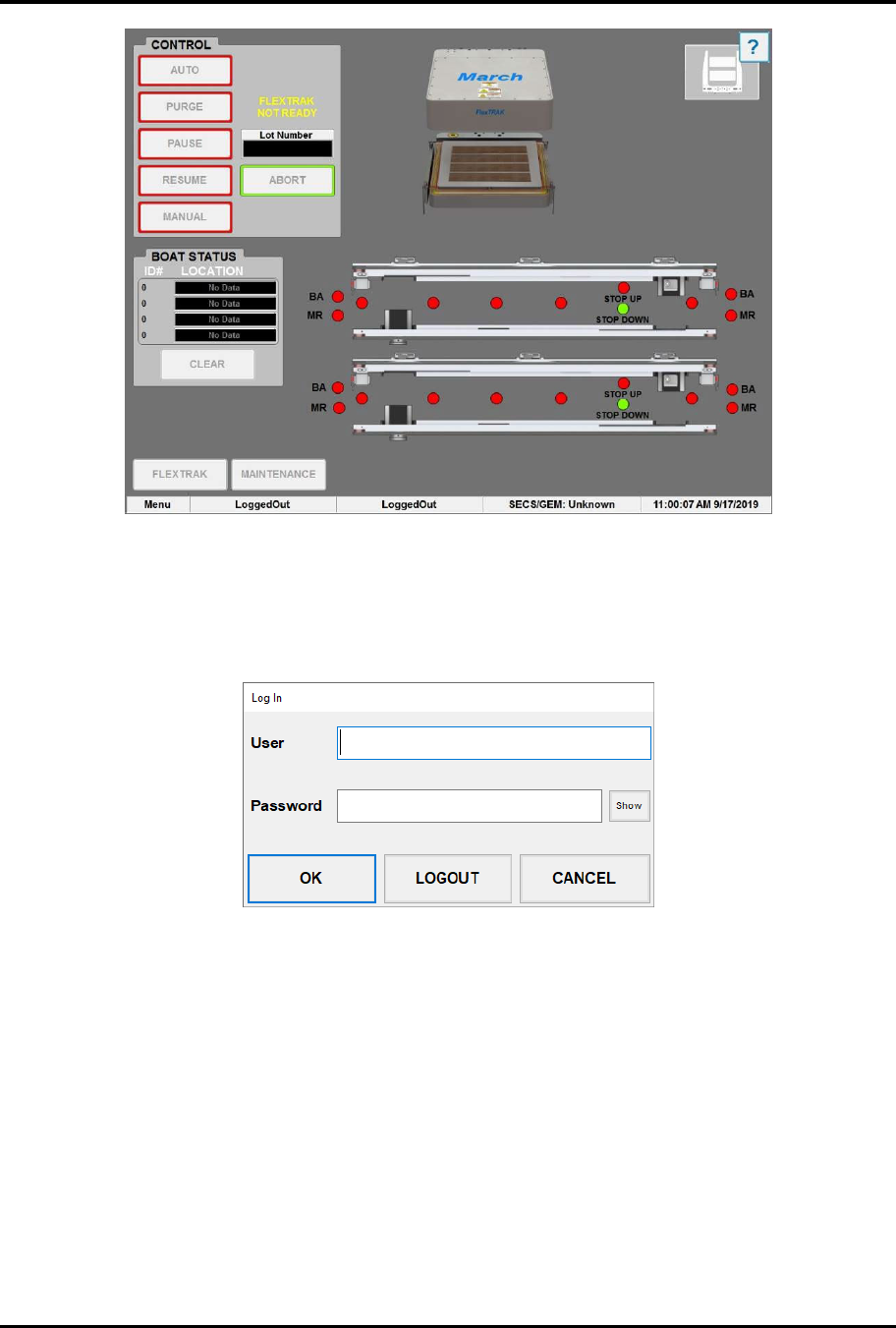
Figure 6-3 MH Overview Screen - Logged Out
4. Touch the text LoggedOut on the status line at the bottom of the MH Overview screen
(Figure 6-3).
„ The Login Form dialog box appears (Figure 6-4).
Figure 6-4 Login Form Dialog Box
5. Log onto the system by entering your appropriate user log-on account name and password
and touching OK (Figure 6-5). Refer to the FlexTRAK Series Installation, Operation, and
Maintenance manual for password set-up.
?
NOTE When the system arrives from the factory, the default usernames are Engineer,
SuperTech, Tech, Operator1, and Operator2. No passwords are necessary.
Touch OK.
FlexTRAK Series 2MB Material Handler Addendum Operations
© 2023 Nordson Corporation 6-5
Figure 6-5 MH Overview Screen - Logged On
FlexTRAK Series 2MB Material Handler Addendum Operations
6-6 © 2023 Nordson Corporation
6.5 Material Handler Homing Routine
The material handling system must perform a homing routine in order to be operational. There are
five (5) axes that must reach home before the system can reset to a safe position.
CAUTION! Simultaneous motion of all drives may occur while the material
handling system performs a homing routine.
The homing routine contains of the following steps:
1. The upper gripper travels vertically along its Z-axis.
2. The upper Z-axis home sensor indicates that it has reached its upper limit.
3. Once the upper gripper reaches its upper limit, it travels horizontally along the
Y-axis to the upper gripper Y-axis home sensor.
4. The lower gripper travels vertically along the Z-axis. The lower Z-axis home sensor
indicates that it has reached its lower limit.
5. Once the lower gripper reaches its upper limit, it travels horizontally along the
Y-axis to the lower gripper Y-axis home sensor.
6. Both the upper and lower gripper assemblies are now located towards the front of the
system with both the Y- and Z-axes limits met. This is the home position for the upper and
lower gripper assemblies.
7. The conveyor's separator travels horizontally along the Y-axis until its home sensor
indicates that it has reached its limit.
8. The assembly resets back to its last known pick and place positions.
9. The gripper positioned at the chamber performs a “pick at chamber” to ensure no carriers
are present.
10. Both carrier stops extend.
The system is ready for use.
6.6 Automatic (Auto) Mode
Automatic mode is normally used for production operations requiring limited operator intervention. In
automatic mode, workpieces are continually processed until system operations are stopped.
This section is intended for system operators who typically run process recipes in automatic mode.
WARNING! Check to make sure there are no parts on the conveyor or in the
chamber before clicking on AUTO. The system will
not operate until all carriers are manually removed
from the system.