FlexTRAK 2MB Material Handler Addendum Rev 05.pdf - 第73页
FlexTRAK Series 2MB Mater ial Handler Adden dum Tour of HMI Softw are for the Material Handler © 2023 Nordson Corporation 5-7 Table 5-6 Material Handling (MH) Overview S creen Controls and Indicators Item Name Des cripti…
FlexTRAK Series 2MB Material Handler Addendum Tour of HMI Software for the Material Handler
5-6 © 2023 Nordson Corporation
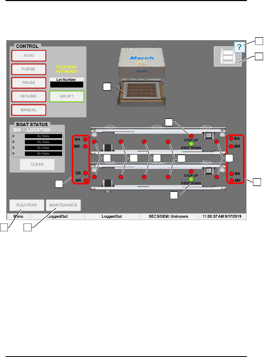
5.4 Material Handler Overview Screen
The Material Handler (MH) Overview screen displays all operational aspects of the material handler and
its functional components.
Figure 5-4 Material Hander (MH) Overview Screen
9
5
3
3
12
13
11
6
4
7
8
10
1
2

FlexTRAK Series 2MB Material Handler Addendum Tour of HMI Software for the Material Handler
© 2023 Nordson Corporation 5-7
Table 5-6 Material Handling (MH) Overview Screen Controls and Indicators
Item Name Description
1 FLEXTRAK
Touch to return to the FlexTRAK Plasma Module (PM) Overview
screen.
2 MAINTENANCE
Touch to open the Maintenance Master screen. Maintenance screens
give access to manual mode controls, shuttler controls, conveyor
controls, digital I/O displays, and system displays.
3 SMEMA LEDS
BOARD AVAILABLE: This indicator toggles green or red to indicate if
the Upstream Material Handler has a workpiece available. BOARD
AVAILABLE can also indicate that material is upstream, or that the
FlexTRAK-2MB has material, depending on whether it is on the left or
right, respectively.
MACHINE READY: This indicator toggles green or red to indicate if
the FlexTRAK-2MB system is ready to receive a workpiece.
4 DETECT 1 LEDS
This LED is located on each conveyor and indicates that a part has
entered the system. The LED is green when the sensor is active. Each
lane is independently controlled, see 4.3.1.4 Lane Position Sensors.
5 DETECT 2 LEDS
This LED is located on each conveyor and indicates a part is on the
conveyor. The LED is green when the sensor is active. Each lane is
independently controlled, see 4.3.1.4 Lane Position Sensors.
?
NOTE Each lane is independently controlled.
6 DETECT 3 LEDS
This LED is located on each conveyor and indicates a part is on the
conveyor. The LED is green when the sensor is active. Each lane is
independently controlled. For a full description of this sensor, see
4.3.1.4 Lane Position Sensors.
?
NOTE Each lane is independently controlled.
7 DETECT 4 LEDS
This LED is located on each conveyor and indicates a part is on the
conveyor. The LED is green when the sensor is active. Each lane is
independently controlled, see 4.3.1.4 Lane Position Sensors.
?
NOTE Each lane is independently controlled.
8
LANE 2 CARRIER
STOP LEDS
Indicates the position of the carrier stop cylinder. The LED is green
when the sensor is active, see 4.3.1.6 Carrier Stops.
?
NOTE Each lane is independently controlled.
9
LANE 2 CARRIER
STOP LEDS
Indicates the position of the carrier stop cylinder. The LED is green
when the sensor is active, see 4.3.1.6 Carrier Stops.
?
NOTE Each lane is independently controlled.
10 DETECT 5 LEDS
Indicates that a part has left the system. The LED is green when the
sensor is active, see 4.3.1.4 Lane Position Sensors.
?
NOTE This LED is also located on Lane 2. Each lane is
independently controlled.
11 GRIPPER STATUS Graphically displays the status of the grippers.
12
HELP
Refer to the HMI Software User Guide for more information on the
Helper feature.
13
REACTION
CHAMBER
At the center of the screen is a dynamic representation of the system.
When the reaction chamber is open, the reaction chamber electrode is
displayed, and when the reaction chamber is closed, the reaction
chamber lid is displayed. When closed, process carrier information is
displayed indicating if process carriers are present or not.
FlexTRAK Series 2MB Material Handler Addendum Tour of HMI Software for the Material Handler
5-8 © 2023 Nordson Corporation
Item Name Description
Control
AUTO Touch to place the MH in Auto mode.
PURGE
Touch to stop incoming process carriers and purge all remaining
process carriers from the system after processing them.
PAUSE Touch to temporarily suspend operation of the system.
RESUME Touch to resume operation after a paused condition.
MANUAL Touch to place the MH in Manual mode.
LOT NUMBER
Displays the name of the current data logging file. Click to open a
dialog box where you can enter a new data logging filename.
ABORT
Touch to stop incoming process carriers and cease operation of the
MH. Boat ID Status is also aborted.
Boat Status
ID#
Displays the number given to a process carrier upon entering the
system. The system sequentially numbers the process carriers in auto
mode.
LOCATION
Displays a process carrier's location as it moves through the system.
Upon entering the system, one of the following descriptions displays in
the LOCATION field:
„
NO DATA - displays when either a process carrier is no longer
tracked, or when only one process carrier has entered a lane
and the other lane is empty.
„
TOP GRIP
„
BOT GRIP
„
CHAMBER
„
CONVEYOR
?
NOTE Text color indicates treated/untreated. Green (Lime) if
untreated, Purple (Magenta) if treated.
CLEAR Touch to clear the process carrier tracking information.