FlexTRAK 2MB Material Handler Addendum Rev 05.pdf - 第52页
FlexTRAK Series 2MB Mater ial Handler Adden dum System Compo nents 4-8 © 2023 Nordson Corporati on 4.3 Material H andler ( MH) The FlexTRAK-2 MB’s Material Handler (MH) co nveys parts from an upstre am system to the plas…
FlexTRAK Series 2MB Material Handler Addendum System Components
© 2023 Nordson Corporation 4-7
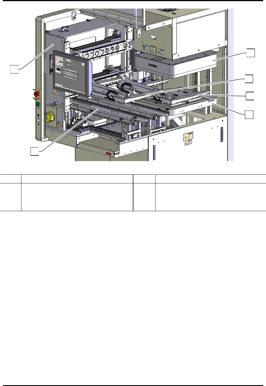
Item Description Item Description
1
Shuttler Assembly
4
Bottom Gripper Arm
2
Dual Lane Conveyor
5
Top Gripper Arm
3
Reaction Chamber Base Assembly
6
Reaction Chamber Lid Assembly
Figure 4-6 FlexTRAK-2MB Cutaway View of the MH Internals
1
2
3
5
4
6
FlexTRAK Series 2MB Material Handler Addendum System Components
4-8 © 2023 Nordson Corporation
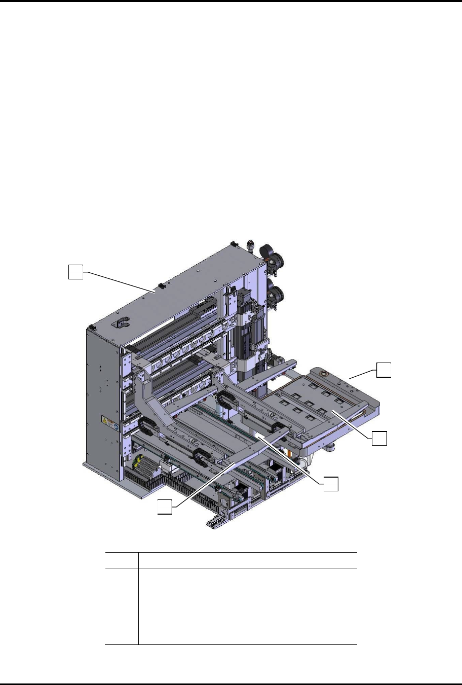
4.3 Material Handler (MH)
The FlexTRAK-2MB’s Material Handler (MH) conveys parts from an upstream system to the plasma
processing chamber, and then to a downstream system (Figure 4-7).
Parts are conveyed from the upstream system to the gripper pick position, where the MH gripper
assembly delivers the carriers to and from the FlexTRAK plasma system for treatment, and then to a
downstream system.
The FlexTRAK-2MB’s MH Overview screen displays a real-time graphical interface representing all
sensors, signals, and motion. The MH assigns each carrier a unique process carrier ID# in order to track
the carriers as they move through the system. The MH can be operated in automatic mode or in manual
mode.
The MH system’s two major components are listed below:
q Dual Lane Conveyor
q Shuttler Assembly
Item Description
1 Shuttler Assembly
2 Dual Lane Conveyor
3 Upper Gripper
4 Lower Gripper
5 Chamber Base
Figure 4-7 FlexTRAK-2MB Material Handling System
2
1
3
4
5
FlexTRAK Series 2MB Material Handler Addendum System Components
© 2023 Nordson Corporation 4-9
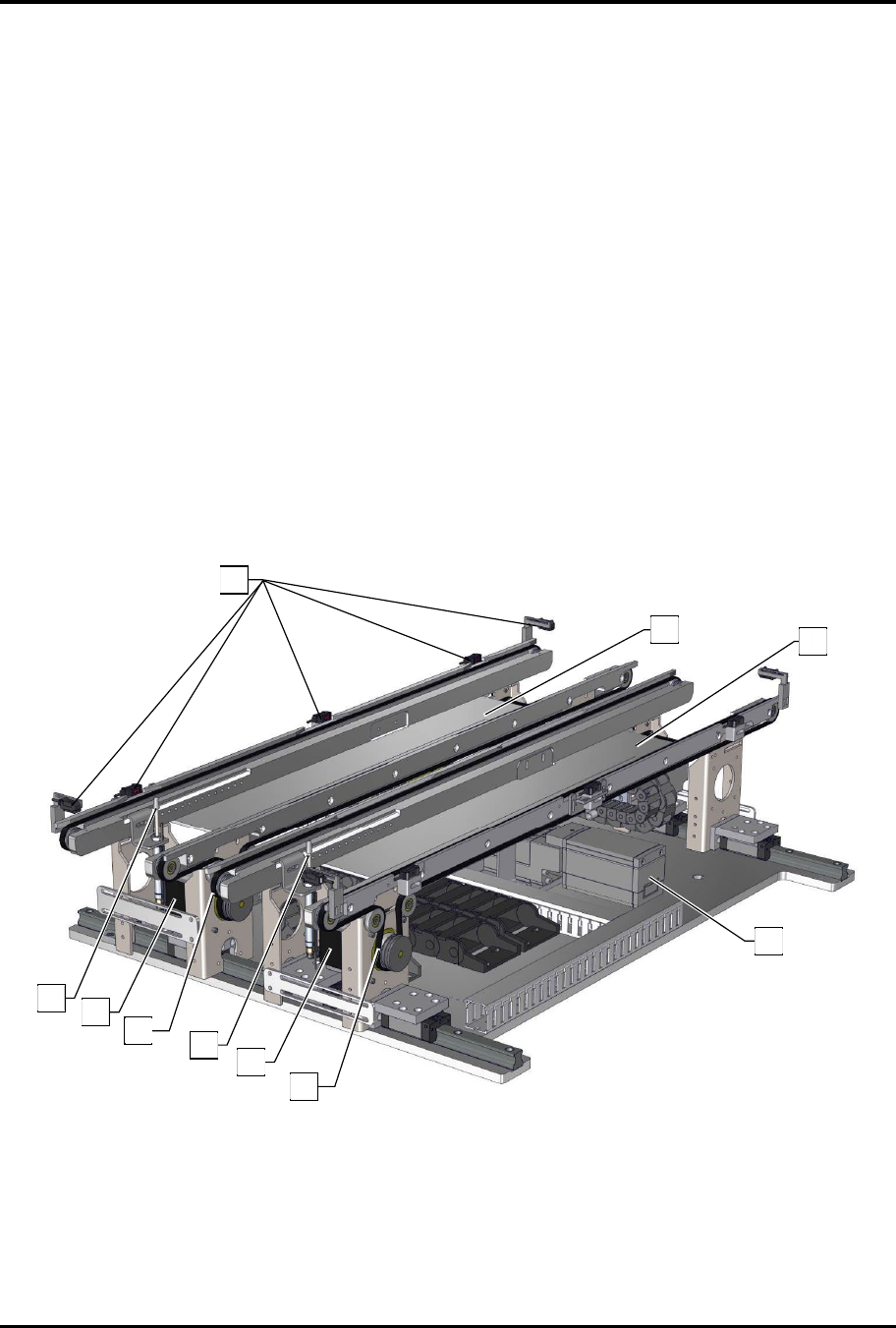
4.3.1 Dual Lane Conveyor
The standard system features a SMEMA compatible dual lane conveyor. Each lane consists of two (2) rail
assemblies which include a high temperature belt, a stepper motor, a pneumatic carrier stop, roller bearing
assemblies and a belt tensioner. Each lane has sensors to track the part’s location throughout the entire
length of the conveyor. The number of sensors varies, depending upon the size of the process carrier.
There are three dual-lane conveyor configurations, which are defined in the following paragraphs.
?
NOTE Systems designed to accommodate extra wide process carriers may require the removal
of the second lane resulting in a single-lane conveyor.
4.3.1.1 Fully Adjustable Dual-Lane Conveyor
In this configuration, Lane 1 is a fixed assembly, manually aligned, leveled, and secured at the factory. It
is used during initial setup to align both the upstream and downstream systems (Figure 4-8). It is typically
used with fixed dual-lane systems upstream and downstream. Parts can be delivered at a teachable lane
spacing and the separator lane adjusts the lane spacing required for plasma processing.
Lane 2 is closest to the processing chamber, also known as the separator. This lane is controlled by a
linear actuator, and its positions are taught using the FlexTRAK-2MB software, see 5.5.1 Axis Status
Screen.
Figure 4-8 Fully Adjustable Dual-Lane Conveyor
1
2
3
4
5
7
6
3
4
5