FlexTRAK 2MB Material Handler Addendum Rev 05.pdf - 第31页
FlexTRAK Series 2MB Mater ial Handler Adden dum Safety © 2023 Nordson Corporation 2-17 Figure 2-8 FlexTRAK-2M B Center of Mass (approximate) 800 mm (31.50 in.) 350 mm (13.70 in.) 660 mm (26.00 in.) 800 mm (31.50 in.) Cen…
FlexTRAK Series 2MB Material Handler Addendum Safety
2-16 © 2023 Nordson Corporation
2.10.5 Seismic Requirements
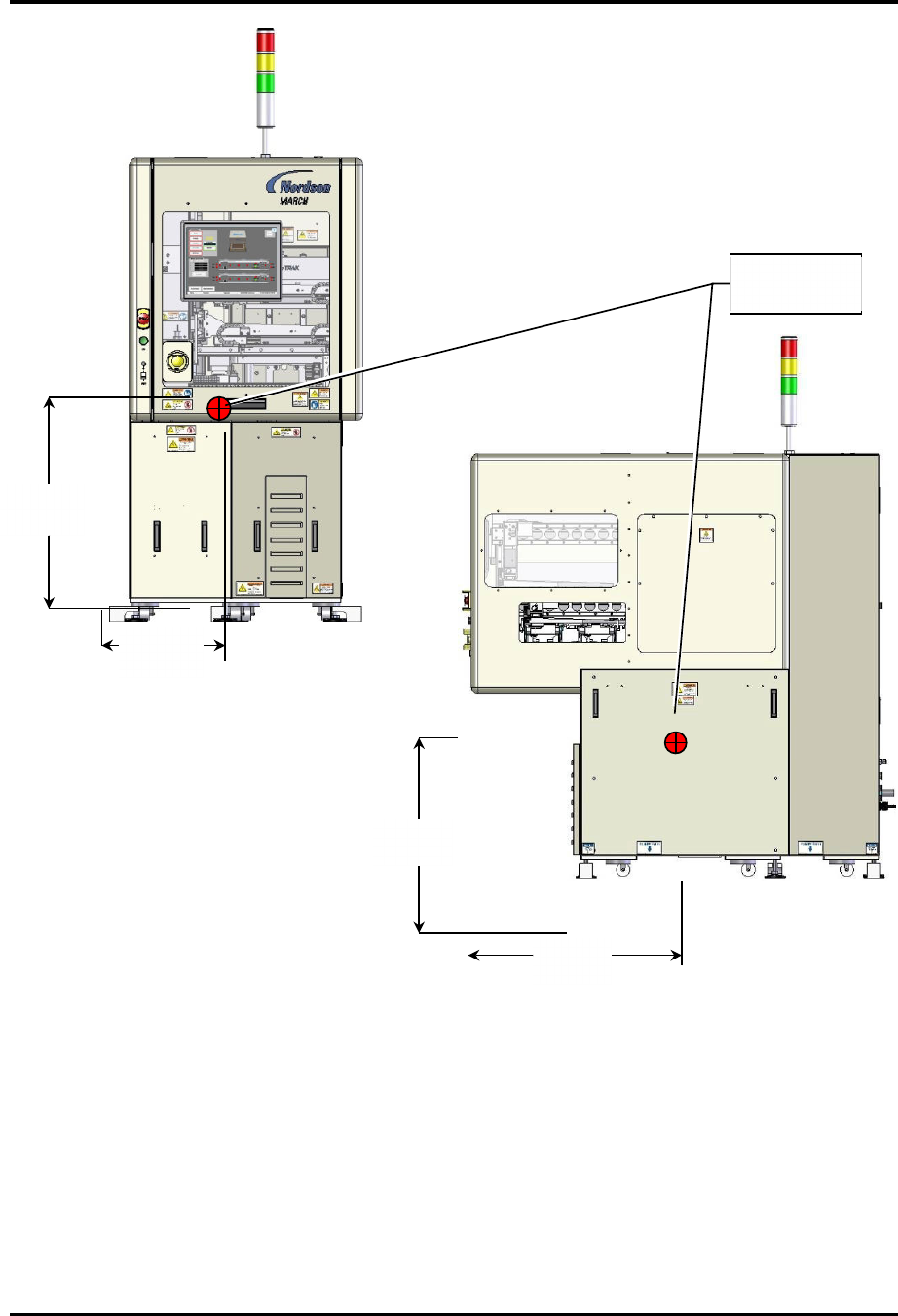
Figure 2-7 and Figure 2-8 show the weight distribution and center of mass for the FlexTRAK-2MB
system.
Figure 2-7 FlexTRAK-2MB System - Weight Distribution (approximate)
192 lbs.
(87 kg)
280lbs.
(127 kg)
209 lbs.
(95 kg)
259 lbs.
(117 kg)
FlexTRAK Series 2MB Material Handler Addendum Safety
© 2023 Nordson Corporation 2-17
Figure 2-8 FlexTRAK-2MB Center of Mass (approximate)
800 mm
(31.50 in.)
350 mm
(13.70 in.)
660 mm
(26.00 in.)
800 mm
(31.50 in.)
Center of
Mass

FlexTRAK Series 2MB Material Handler Addendum Safety
2-18 © 2023 Nordson Corporation
2.11 Service Shutdown
Before performing any service or parts replacement, the FlexTRAK-2MB system should be shutdown
as follows:
To shutdown for service:
1. Shutdown the computer.
2. Press the red EMO button (Figure 2-5) to turn OFF the machine.
3. Perform a system lockout, see 2.7.1 System Lockout.
2.11.1 System Lockout
During maintenance and servicing tasks, prevent injury to personnel by locking out and tagging out
system power and gas supplies.
Refer to the FlexTRAK Series Installation, Operations, and Maintenance manual for the lockout/tagout
procedure.
?
NOTE The purpose of any system lockout is to help avoid injury or system damage due to
unexpected energizing of equipment, start up, or the release of stored energy during
repair, maintenance, and operation of equipment. Situations where lockout practices
might not be required are when troubleshooting electrical, pneumatic, or hydraulic
components or assemblies that make de-energizing the whole system impractical.
2.11.2
31B31B
Restoring the System to Service
To restore the system to service:
1. Make sure all doors, panels, and guards are in place.
2. Unlock and remove the padlock on the lockout devices.
3. Remove all warning tags.
4. Reconnect the electrical plug to facility power.
5. To start the system, twist the red EMO/Off button counterclockwise until it pops out and
press the green ON button (Figure 2-5).