FlexTRAK 2MB Material Handler Addendum Rev 05.pdf - 第136页
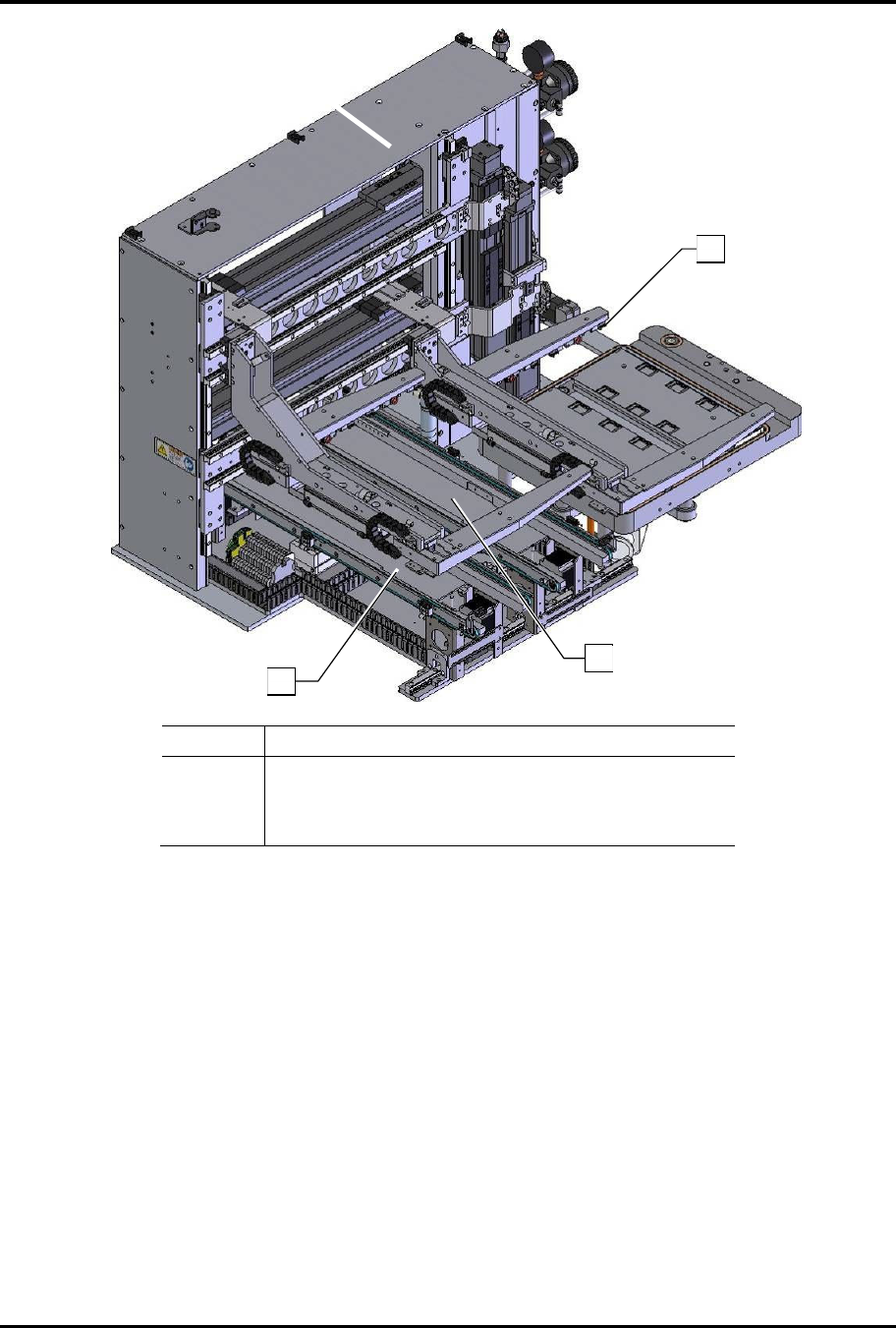
FlexTRAK Series 2MB Mater ial Handler Adden dum Maintenance 8-8 © 2023 Nordson Corporati on Item Description 1 Gripper Fingers 2 Conv e yor, Lane 1 3 Conv e yor, Lane 2 Figure 8-1 Shuttler Assembly 3 1 2
© 2023 Nordson Corporation 8-7
8 Maintenance
8.1 Overview
This section explains recommended periodic maintenance required on the major 2MB Material Handler
components in the list below.
8.2 Safety First
Before performing any of the procedures in this section, please review the precautions found in
Section 2 - Safety.
WARNING! To prevent exposure to hazardous voltages, RF radiation,
process gases, and pneumatic pressures, the system should be locked out and
tagged out during maintenance procedures, see 2.11 Service Shutdown.
CAUTION! Only trained and authorized personnel should perform
maintenance tasks on the 2MB Material Handler system.
8.3 Record Keeping
Record the type of procedure performed in maintenance records for the material handling system. This
includes dates, part numbers/serial numbers of replaced parts, names of technicians, and other pertinent
data.
8.4 Recommended Shuttler Maintenance
User-performed maintenance required for the shuttler system is minimal. However, regular attention to
the suggested maintenance items will help to ensure proper operation and maximum availability of
the system. Refer to your FlexTRAK 2MB Electrode Fixturing Addendum for details.
?
NOTE The maintenance interval depends on the level of system use. Specified intervals are for
systems averaging 12 or more hours per day (see Table 8-1).
Table 8-1 Recommended Shuttler Maintenance Procedures
Item Frequency Instructions Comments
Gripper Fingers As needed
Wipe down both mounting surfaces
with a soft cloth and isopropyl
alcohol, see 8.4.2 Changing the
Gripper Fingers and Detection
Switches.
8 each per assembly. Evaluated
based on excess wear.
Conveyor Six Months
Tension Conveyor Belts, see 8.4.3
Tensioning the Conveyor Belts
2 each per assembly. Evaluated
based on excess wear.
Conveyor As needed
Replace Conveyor Belts, see 8.4.4
Replacing the Conveyor Belts.
2 each per assembly. Evaluated
based on excess wear.
FlexTRAK Series 2MB Material Handler Addendum Maintenance
8-8 © 2023 Nordson Corporation
Item Description
1 Gripper Fingers
2 Conveyor, Lane 1
3 Conveyor, Lane 2
Figure 8-1 Shuttler Assembly
3
1
2

FlexTRAK Series 2MB Material Handler Addendum Maintenance
© 2023 Nordson Corporation 8-9
8.4.1 Removing the Gripper Assemblies
?
NOTE It is not necessary to remove the gripper assemblies for cleaning purposes. However, you
can remove the gripper assemblies for inspection, troubleshooting, or part replacement.
After you have removed the gripper assemblies, you can service them on a bench-top
table.
Tools and Materials Needed:
q
4 mm
Allen
Key
q
Soft Cloth and Cotton Swabs
q
Isopropyl Alcohol
q
Removable Thread Locker
?
NOTE See Appendix A for a list of replacement shuttler gripper parts.
For ease of reinstallation, note the location, orientation, and routing of the wiring, tubing,
and any additional components before removing them.
Retain all components and fasteners removed during this procedure in an orderly manner
and in a safe location for reinstallation or shipment back to Nordson.
To remove the shuttle gripper assembly:
CAUTION! This procedure should only be performed by a trained service
technician.
1. Perform a service shutdown, see 2.11 Service Shutdown.
2. Open the front door.
3. Pull the gripper assembly toward the front of the system.
4. Remove the electrical wires and air lines from the cable tie located at the mounting plate.
5. Disconnect the electrical connector located at the center of the gripper.
6. Disconnect both air lines from the gripper actuator at the push-in connectors.
7. Using a 4 mm Allen key, locate and remove the three mounting screws from the mounting
plate.
„ Even though the mounting plate is pinned to the Y-Axis drive assembly, use caution
when removing the last bolt, because the assembly could dislodge from the alignment
pins and fall.
8. Perform the necessary service or inspection, such as replacement of the gripper fingers.
9. Wipe down both mounting surfaces using a soft cloth and isopropyl alcohol.
10. Reassemble in reverse order.
11. Check alignment of the gripper assembly by manually picking and placing process carriers
to ensure proper reassembly and repeatability. Adjust if necessary.