FlexTRAK 2MB Material Handler Addendum Rev 05.pdf - 第41页
FlexTRAK Series 2MB Mater ial Handler Adden dum Installation © 2023 Nordson Corporation 3-9 5. Connect the following communication cables, as applicable (Figure 3-3). a. SMEMA connectors for the upstream and downstream m…
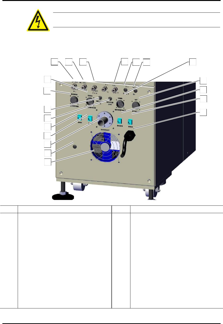
FlexTRAK Series 2MB Material Handler Addendum Installation
3-8 © 2023 Nordson Corporation
WARNING! To prevent shock hazards to personnel, only a grounded power
plug should be installed on the power cord.
3. Connect the main power cord to the facility AC power source.
4. Attach the facility exhaust line to the exhaust port.
Item Description Item Description
1
Pump Purge Inlet (N
2
) (Pump Purge option
only)
12 Main Power Cord
2 System Pressure (CDA) 13 Cooling Fan
3 Chamber Purge Gas (CDA/N
2
) 14 Chamber Drain Port (Optional)
4 Gas 1 Inlet 15 Exhaust Port
5 Gas 2 Inlet 16 Local Area Network Ethernet Port
6 Gas 3 Inlet (Optional) 17
Downstream Material Handler Ethernet
Port
7 Gas 4 Inlet (Optional) 18 Water Out Port (Optional)
8 Upstream Material Handler Interface 19 Water In Port (Optional)
9 Upstream SMEMA Connector 20 Downstream SMEMA Connector
10 SECS/GEM Host Ethernet Port 21 Downstream Material Handler Interface
11
Upstream Material Handler
Ethernet Port
Figure 3-3 Facility Connections
2
1
1
3
1
2
3
5
6
7
1
2
19
18
20
1
7
1
6
1
5
1
4
8
9
10
11

FlexTRAK Series 2MB Material Handler Addendum Installation
© 2023 Nordson Corporation 3-9
5. Connect the following communication cables, as applicable (Figure 3-3).
a. SMEMA connectors for the upstream and downstream machines.
b. Interface connectors for the upstream (UMH Interface) and downstream (DMH
Interface) material handler.
c. Ethernet connector for the SECS/GEM host (optional).
3.7 Initial Start-up Procedure
CAUTION! Certain process gases selected for use with this equipment may
be hazardous. Consult your facilities safety officer to ensure proper
precautionary steps are taken before these gases are connected or used.
To perform initial system start-up:
1. Adjust facility gas supplies to the following pressures:
„ Main Air (CDA): 80 to 100 psi (5.5 to 6.9 bar)
„ Chamber Purge Gas (N
2
): 10 to 100 psi (0.7 to 6.9 bar)
„ Process Gasses: 10 to 15 psi (0.7 to 1.0 bar).
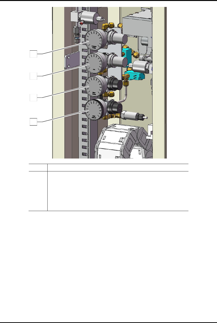
2. Remove the rear access panel and adjust the regulators (Figure 3-3):
„ Chamber Purge Gas (N
2
): 10 to 30 psi (0.7 bar to 2.1 bar)
„ Main Air (CDA): 60 to 80 psi (4.1 to 5.5 bar)
„ Optional Pump Purge Gas (N
2
): 5 psi (0.3 bar) maximum
FlexTRAK Series 2MB Material Handler Addendum Installation
3-10 © 2023 Nordson Corporation
Item Description
1 Chamber Purge Gas (N
2
) Regulator and Gauge (30 psi max)
2 Main Air (CDA) Regulator and Gauge (80 psi max)
3 Vacuum Pump Purge (N
2
) Regulator and Gauge (5 psi max)
4
Optional Exhaust Purge (H
2
) Gauge & Regulator
(10 psi max) (refer to the Hydrogen Gas documentation provided
with the H2 option)
Figure 3-4 Air and Purge Gas Regulator/Gauge Location
4
3
2
1