FlexTRAK 2MB Material Handler Addendum Rev 05.pdf - 第61页
FlexTRAK Series 2MB Mater ial Handler Adden dum System Compo nents © 2023 Nordson Corporation 4-17 4.3.2.1 Gripper Assemb lies The gripper assembly is the devi ce used to deliver parts to the chamber and the conveyor. Th…
FlexTRAK Series 2MB Material Handler Addendum System Components
4-16 © 2023 Nordson Corporation
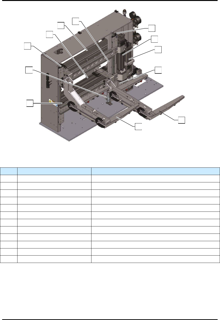
Figure 4-11 Shuttler System
Table 4-5 Shuttler System Components
Item Description Function
1 Upper Z-axis Home Sensor Indicates that the upper gripper is home in the Z-axis.
2 Upper Z-axis Linear Actuator Positions the upper gripper along the Z-axis.
3 Lower Z-axis Linear Actuator Positions the lower gripper along the Z-axis.
4 Lower Z-axis Home Sensor Indicates that the lower gripper is home in the Z-axis.
5 Lower Gripper Delivers parts to and from the process chamber.
6 Upper Gripper Delivers parts to and from the process chamber.
7 Lower Y-axis Home Sensor Indicates that the lower gripper is home in the Y-axis.
8 Lower Z-axis Pneumatic Assist Used to reduce the load on the lower Z-axis actuator.
9 Upper Y-axis Home Sensor Indicates that the upper gripper is home in the Y-axis.
10 Lower Y-axis Linear Actuator Positions the lower gripper along the Y-axis.
11 Upper Y-axis Linear Actuator Positions the upper gripper along the Y-axis.
12 Upper Z-axis Pneumatic Assist Used to reduce the load on the upper Z-axis actuator.
5
6
9
11
10
12
1
2
3
4
8
7
FlexTRAK Series 2MB Material Handler Addendum System Components
© 2023 Nordson Corporation 4-17
4.3.2.1 Gripper Assemblies
The gripper assembly is the device used to deliver parts to the chamber and the conveyor. There is an
upper gripper assembly and a lower gripper assembly. The gripper assembly is pneumatically controlled
and designed to lift the part without gripping it from the sides by using hard stops to limit the closed
position. Only the detection switches apply a very low force on the part while carried by the gripper, see
4.3.2.2 Pneumatic Actuator. The gripper assemblies extend and retract to the factory-set open and closed
limits and travel in both the Y- and Z-axes. Each gripper assembly is driven by an independent linear
actuator in combination with a pneumatic cylinder assist.
Gripper assembly movements are coordinated to work simultaneously, maximizing part delivery to both
the process chamber and the conveyor. The upper gripper always travels over the top of the lower gripper.
The coordinated movements are validated by home sensors located along the Y- and Z-axes. These
positions must be valid before the MH can operate. There are two user-taught positions per gripper
assembly: At Chamber and At Conveyor, see 6.5 Material Handler Homing Routine.
Upper Gripper
TOP AT CHAMBER
TOP AT CONVEYOR
Upper Gripper
BOT AT CHAMBER
BOT AT CONVEYOR
All other factory teach points, with the exception of the linear actuator speed, cannot be modified.
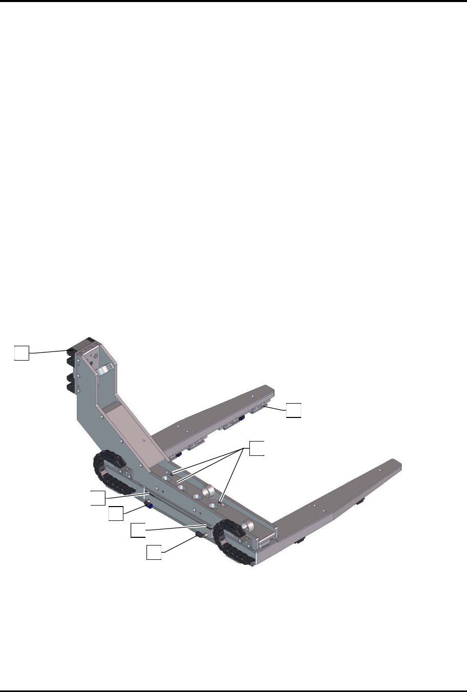
Figure 4-12 Gripper Assembly (Top View)
See Table 4-6 for callout descriptions.
9
2
5
4
5
4
3
FlexTRAK Series 2MB Material Handler Addendum System Components
4-18 © 2023 Nordson Corporation
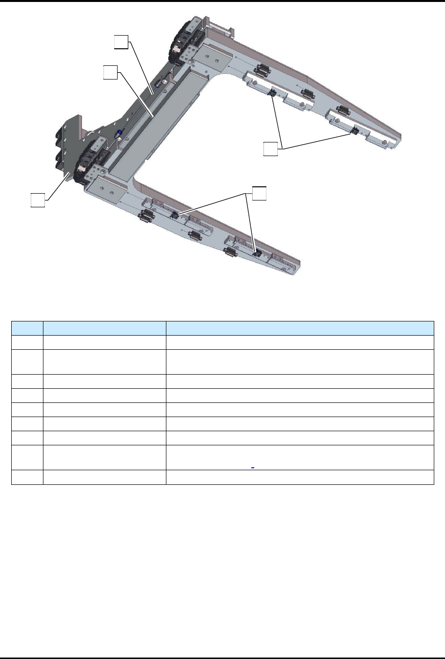
Figure 4-13 Gripper Assembly (Bottom View)
Table 4-6 Gripper Assembly Components
Item
Description
Function
1 Mounting Plate Quick disconnect for servicing.
2 Gripper Fingers
Allows the gripper to engage the workpiece, see 4.3.2.4
Gripper Fingers.
3 Leveling Screws Adjustment screws for leveling the gripper assembly.
4 Air Supply Input/Output Delivers low pressure air for actuation.
5 Open/Close Sensors Indicates gripper open/closed.
6 Actuator Cover Cover to enclose the actuator.
7 Pneumatic Actuator Opens and closes the gripper (partial view).
8 Detection Switches
Indicates part detection. Two switches per carrier, see 4.3.2.3
Detection Switches.
9 Ball Bearing Allows the gripper assembly to travel along the Y-axis.
Both assemblies are identical and mount independently via a cantilever arm to their respective drive axis.
The entire assemblies can be removed and replaced for servicing at the mounting plate. The arms will
disconnect, leaving the Y-axis ball bearing slides attached to the MH. Servicing is made easy by the use
of quick disconnects and pinned locations to ensure proper alignment for reattachment. Fine adjustments
can be made to level the assembly at installation using the three adjustable leveling screws. Each gripper
assembly should be leveled relative to the chamber electrode.
6
1
7
8
8