FlexTRAK 2MB Material Handler Addendum Rev 05.pdf - 第57页
FlexTRAK Series 2MB Mater ial Handler Adden dum System Compo nents © 2023 Nordson Corporation 4-13 4.3.1.3 Fixed Position Dual -Lane Conveyor In this confi guration, Lane 1 is fixed to Lane 2, and there is no width adju …

FlexTRAK Series 2MB Material Handler Addendum System Components
4-12 © 2023 Nordson Corporation
Table 4-2 Adjustable Single-Unit Dual-Lane Conveyor Components (Front View)
Item Name Description
1 Lane 1
Fixed position relative to Lane 2. Lane position is adjustable along
the Y-axis, see 4.3.1.3 Fixed Position Dual-Lane Conveyor.
2 Lane 2
Fixed position relative to Lane 1. Lane position is adjustable along
the Y-axis, see 4.3.1.3 Fixed Position Dual-Lane Conveyor.
3 Stepper Motor
The stepper motors supply power to the belt assemblies. There are
two stepper motors per lane. Both motors are synchronized to
operate together and drive the carriers down the length of the
conveyor.
4
Lane Position
Sensors
The lane position sensors detect parts throughout the length of the
conveyor. Five sensors per lane ensure traceability of the carrier, see
4.3.1.4 Lane Position Sensors.
5
Separator
Actuator
The separator actuator controls the position of the entire dual lane
assembly. There are three teachable positions: Lane 1 conveyance,
Lane 2 conveyance, and grip. Home position is built into the actuator,
see 4.3.1.5 Separator Actuator.
6 Belts
High temperature belts move the parts through the system. There are
two belts per lane, see 4.3.1.7 High Temperature Belts.
7 Carrier Stops
The pneumatic carrier stop prevents over travel of the part. There is
one carrier stop per lane, see 4.3.1.6 Carrier Stops.
FlexTRAK Series 2MB Material Handler Addendum System Components
© 2023 Nordson Corporation 4-13
4.3.1.3 Fixed Position Dual-Lane Conveyor
In this configuration, Lane 1 is fixed to Lane 2, and there is no width adjustment by the actuator. Lane 1
and Lane 2 are a single fixed assembly, aligned, leveled, and secured at the factory (Figure 4-10). The
two-lane assembly position is not adjustable. It is typically used with adjustable dual lane conveyors
upstream/downstream where the lane spacing can be set equal to the 2MB conveyor.
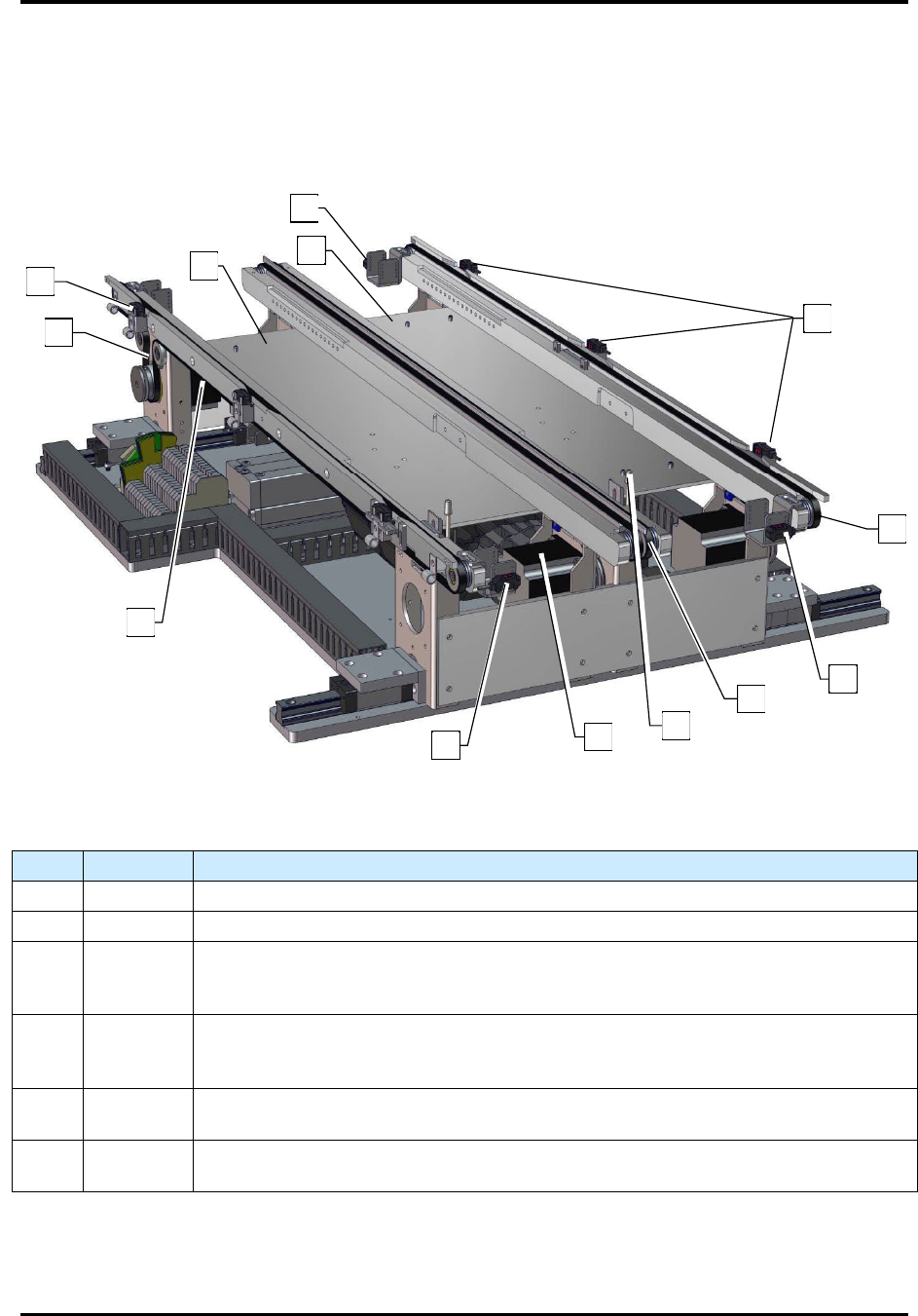
Figure 4-10 Fixed Position Dual-Lane Conveyor
Table 4-3 Fixed Position Dual-Lane Conveyor Components (Front View)
Item Name Description
1 Lane 1 Lane position and lane width are both fixed at the factory
2 Lane 2 Lane position and lane width are both fixed at the factory.
3
Stepper
Motor
The stepper motors supply power to the belt assemblies. There are two stepper
motors per lane. Both motors are synchronized to operate together and drive the
carriers down the length of the conveyor.
4
Lane
Position
Sensors
The lane position sensors detect parts throughout the length of the conveyor. Five
sensors per lane ensure traceability of the carrier, see 4.3.1.4 Lane Position
Sensors.
5 Belts
High temperature belts move the parts through the system. There are two belts per
lane, see 4.3.1.7 High Temperature Belts.
6
Carrier
Stops
The pneumatic carrier stop prevents over travel of the part. There is one carrier stop
per lane, see 4.3.1.6 Carrier Stops.
2
1
4
3
6
5
4
4
4
4
5
5
3

FlexTRAK Series 2MB Material Handler Addendum System Components
4-14 © 2023 Nordson Corporation
4.3.1.4 Lane Position Sensors
As a carrier enters the system, multiple sensors monitor its position along the conveyor. The carrier
positions are displayed in the software as Detect 1-5, see 6.7.4 Manipulating the Lane 2 Conveyor. The
number of sensors for each Detect position is determined by the size of the carrier.
The conveyor will turn on when a board available signal is given by the upstream system and will operate
at the LOAD SPEED set point. If a lane sensor senses something out of sequence, the MH Alarm screen
will prompt an “Unexpected Boat on Lane” alarm, see 9.5 Material Handling Alarms.
Table 4-4 Typical Conveyor Carrier Sequence
Name Description Function
Detect 1 Carrier Entry The Detect 1 sensor activates when a carrier enters the conveyor.
Detect 2
Upstream
System Ready
When the trailing edge of the carrier clears Detect 1 and is sensed by
Detect 2, the SMEMA Upstream System Ready signal toggles and the
conveyor changes to the LOAD SPEED set point. This sensor must be
positioned so during a load in routine, the carrier can be sensed by at
least one of Detect 1, Detect 2, or Detect 3.
Detect 3
Initiate Load in
Time
When the leading edge of the carrier is sensed by Detect 3, it initiates the
LOAD IN TIME timer. The conveyor slows to the Jog speed after the
timer runs for the designated amount of time unless the leading edge of
the carrier is sensed by Detect 4 first. Detect 3 must be active when the
process carrier comes to a stop at the Gripper Pick Position in order for a
carrier to be picked up by the MH gripper assembly.
Detect 4 Stop Belt
This sensor stops the belt operation upon sensing the leading edge of a
carrier. Detect 4 must be active when the process carrier comes to a stop
at the Gripper Pick Position in order for a carrier to be picked up by the
MH gripper assembly.
Detect 5
Stop
Conveyer
When the leading edge of the carrier is sensed by Detect 5, the conveyor
ramps down to the UNLOAD SPEED. Detect 5 must remain off for the
designated amount of time specified in the BOAT OUT DELAY before the
timer can shut off and stop the conveyor. When Detect 5 does not sense
the trailing edge of a carrier for that amount of time, the SMEMA
Downstream Board Available signal toggles and the conveying process is
complete.
?
NOTE Load speed, lane speed, unload speed and timers are set in the FlexTRAK-2MB software,
see 6.7.4 Manipulating the Lane 2.