FlexTRAK 2MB Material Handler Addendum Rev 05.pdf - 第86页
FlexTRAK Series 2MB Mater ial Handler Adden dum Tour of HMI Softw are for the Material Handler 5-20 © 2023 Nordson Corporation 5.5.2 Digi t al Input Status Screen During op eration, you can view the status of all digital…
FlexTRAK Series 2MB Material Handler Addendum Tour of HMI Software for the Material Handler
© 2023 Nordson Corporation 5-19
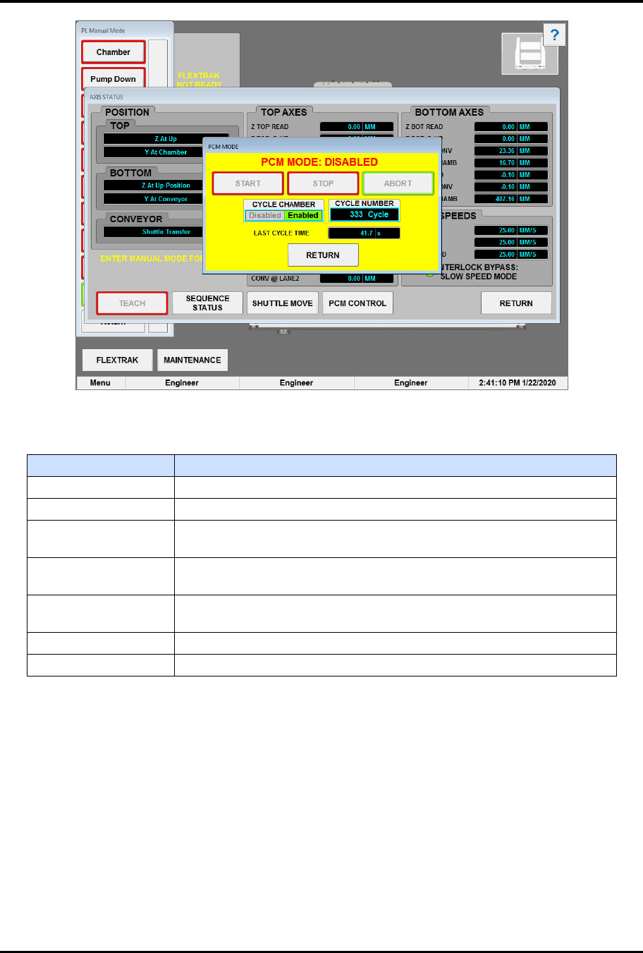
Figure 5-11 PCM Mode Dialog Box - Stop Mode
Table 5-13 PCM Mode Controls and Indicators
Control Description
START Touch START to start PCM mode.
STOP Touch STOP to stop the PCM at the end of the next cycle.
ABORT
Touch ABORT to stop the PCM at the current position. The MH will
finish the current move but not the complete cycle.
CYCLE CHAMBER
Touch DISABLED or ENABLED to toggle between cycling the MH
with or without the chamber.
NUM. CYCLES
Displays the current number of cycles performed by PCM. Click this
field to reset the cycle count.
LAST CYCLE TIME Displays the last cycle time in seconds.
RETURN Touch RETURN to close the PCM Mode dialog box.
FlexTRAK Series 2MB Material Handler Addendum Tour of HMI Software for the Material Handler
5-20 © 2023 Nordson Corporation
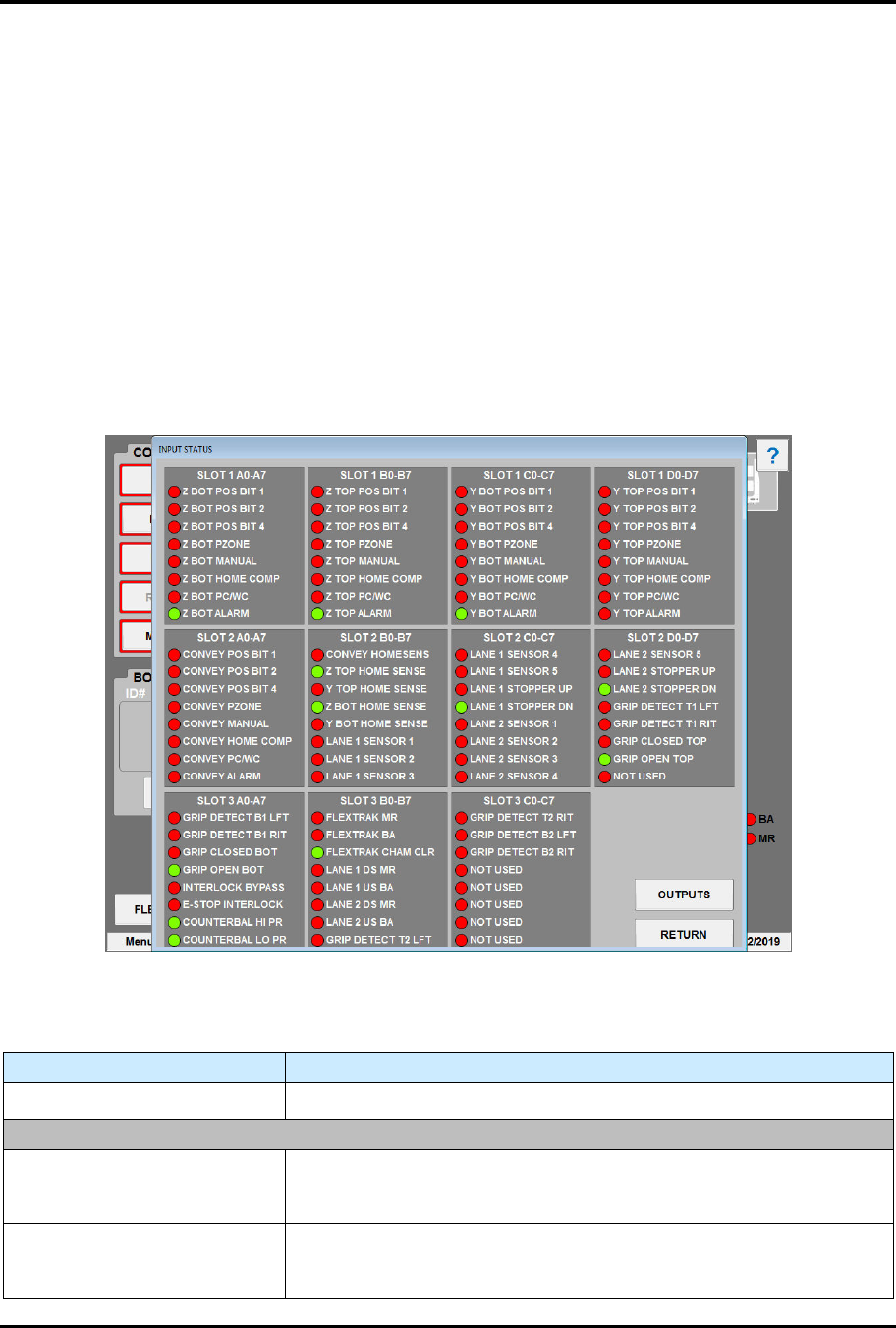
5.5.2 Digital Input Status Screen
During operation, you can view the status of all digital input points of the plasma system’s EPC I/O on
the Input Status screen (Figure 5-12). The Input Status screen can also be useful during troubleshooting to
check if a sensor is active and lit. A red light means the I/O point is off (open/disconnected), and a green
light means that it is on (closed/connected). See Table 5-14 for descriptions of the Input Status screen
controls and indicators.
To access the input status screen:
1. Touch the MAINTENANCE button on the MH Overview screen to access maintenance
commands.
„ The Maintenance Master screen opens (Figure 5-5).
2. Touch the DIGITAL INPUTS button.
„ The Input Status screen opens (Figure 5-12).
Figure 5-12 Input Status Screen
Table 5-14 Input Status Screen Point Descriptions
Control Description
OUTPUTS
Touch to switch to the Output Status screen (Figure 5-13).
SLOT 1 A0-A7
Z BOT POS BIT 1
Indicates the status of the Z-axis Bottom Position Bit 1 sensor. A red
light means the I/O point is off (open/disconnected), and a green light
means that it is on (closed/connected).
Z BOT POS BIT 2
Indicates the status of the Z-axis Bottom Position Bit 2 sensor. A red
light means the I/O point is off (open/disconnected), and a green light
means that it is on (closed/connected).

FlexTRAK Series 2MB Material Handler Addendum Tour of HMI Software for the Material Handler
© 2023 Nordson Corporation 5-21
Control Description
Z BOT POS BIT 4
Indicates the status of the Z-axis Bottom Position Bit 4 sensor. A red
light means the I/O point is off (open/disconnected), and a green light
means that it is on (closed/connected).
Z BOT PZONE
Indicates the status of the Z-axis Bottom PZone sensor. A red light
means the I/O point is off (open/disconnected), and a green light
means that it is on (closed/connected).
Z BOT MANUAL
Indicates the status of the Z-axis Bottom Manual sensor. A red light
means the I/O point is off (open/disconnected), and a green light
means that it is on (closed/connected).
Z BOT HOME COMP
Indicates the status of the Z-axis Bottom Home Comp sensor. A red
light means the I/O point is off (open/disconnected), and a green light
means that it is on (closed/connected).
Z BOT PC/WC
Indicates the status of the Z-axis Bottom PC/WC sensor. A red light
means the I/O point is off (open/disconnected), and a green light
means that it is on (closed/connected).
Z BOT ALARM
Indicates the status of the Z-axis Bottom Alarm sensor. A red light
means the I/O point is off (open/disconnected), and a green light
means that it is on (closed/connected).
SLOT 1 B0-B7
Z TOP POS BIT 1
Indicates the status of the Z-axis Top Position Bit 1 sensor. A red light
means the I/O point is off (open/disconnected), and a green light
means that it is on (closed/connected).
Z TOP POS BIT 2
Indicates the status of the Z-axis Top Position Bit 2 sensor. A red light
means the I/O point is off (open/disconnected), and a green light
means that it is on (closed/connected).
Z TOP POS BIT 4
Indicates the status of the Z-axis Top Position Bit 4 sensor. A red light
means the I/O point is off (open/disconnected), and a green light
means that it is on (closed/connected).
Z TOP PZONE
Indicates the status of the Z-axis Top PZone sensor. A red light
means the I/O point is off (open/disconnected), and a green light
means that it is on (closed/connected).
Z TOP MANUAL
Indicates the status of the Z-axis Top Manual sensor. A red light
means the I/O point is off (open/disconnected), and a green light
means that it is on (closed/connected).
Z TOP HOME COMP
Indicates the status of the Z-axis Top Home Comp sensor. A red light
means the I/O point is off (open/disconnected), and a green light
means that it is on (closed/connected).
Z TOP PC/WC
Indicates the status of the Z-axis Top PC/WC sensor. A red light
means the I/O point is off (open/disconnected), and a green light
means that it is on (closed/connected).
Z TOP ALARM
Indicates the status of the Z-axis Top Alarm sensor. A red light
means the I/O point is off (open/disconnected), and a green light
means that it is on (closed/connected).