FlexTRAK 2MB Material Handler Addendum Rev 05.pdf - 第60页
FlexTRAK Series 2MB Mater ial Handler Adden dum System Compo nents 4-16 © 2023 Nordson Corporation Figure 4-11 Shuttler System Table 4-5 Shuttler System Compon ents Item Description Func tion 1 Upper Z-axis Home Sensor I…

FlexTRAK Series 2MB Material Handler Addendum System Components
© 2023 Nordson Corporation 4-15
4.3.1.5 Separator Actuator
The separator has a home position inherently built into the actuator and teachable positions taught through
the FlexTRAK-2MB software, see 5.5.4 Conveyor Status Screen. The first position is called the Conveyor
Grip and the second is called Conveyance.
1. Conveyor Grip (Grip Pos.) - The Conveyor Grip position moves Lane 2 to a position where
the MH grippers can pick and place parts on and off of the conveyor. The lane space
position relates to the spacing of the gripper fingers as well as the spacing within the plasma
processing chamber where the carriers are to be placed for treatment. For the Fixed Position
Dual-Lane Conveyor system, the conveyor grip position is ignored.
2. Conveyance Position - The Conveyance position moves Lane 2 to a position where the parts
can be transferred to and from the upstream and downstream systems. This position is
taught during setup to ensure that the carrier can be conveyed through the system. It is a
relative position based on Lane 1 after the tool has been aligned with the upstream and
downstream systems. For the Adjustable Single-Unit Dual-Lane Conveyor system, the
single conveyance position is replaced by two conveyance positions--one for each lane. For
the Fixed Position Dual-Lane Conveyor system, the conveyance position is ignored.
4.3.1.6 Carrier Stops
There is one adjustable pneumatic carrier stop per lane. The stops can be adjusted using the flow
controllers located in the FlexTRAK-2MB’s rear enclosure (Figure 4-5). When the conveyor turns on,
both carrier stops engage, and the corresponding LED located on the MH Overview screen glows green.
The stops locate the carrier in a safe position to be picked up by the MH gripper assembly. When the
carrier reaches the Gripper Pick position, both the Detect 3 and Detect 4 sensors must be activated in
order for the carrier to be picked up.
4.3.1.7 High Temperature Belts
There are two high temperature belts per lane. Maximum temperature should not exceed 150 °C. A
qualified technician can adjust the tension periodically for continuous conveyor operation. Belts need to
be replaced periodically, see 8.4.4 Replacing the Conveyor Belts.
4.3.2 Shuttler Assembly
The shuttler assembly is a 4-axis pick and place system. The shuttler utilizes gripper assemblies to deliver
parts conveyed by the conveyor, to and from the plasma processing chamber for treatment.
FlexTRAK Series 2MB Material Handler Addendum System Components
4-16 © 2023 Nordson Corporation
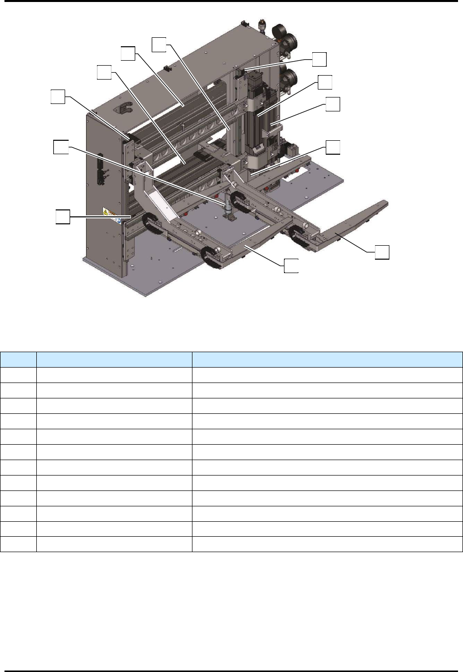
Figure 4-11 Shuttler System
Table 4-5 Shuttler System Components
Item Description Function
1 Upper Z-axis Home Sensor Indicates that the upper gripper is home in the Z-axis.
2 Upper Z-axis Linear Actuator Positions the upper gripper along the Z-axis.
3 Lower Z-axis Linear Actuator Positions the lower gripper along the Z-axis.
4 Lower Z-axis Home Sensor Indicates that the lower gripper is home in the Z-axis.
5 Lower Gripper Delivers parts to and from the process chamber.
6 Upper Gripper Delivers parts to and from the process chamber.
7 Lower Y-axis Home Sensor Indicates that the lower gripper is home in the Y-axis.
8 Lower Z-axis Pneumatic Assist Used to reduce the load on the lower Z-axis actuator.
9 Upper Y-axis Home Sensor Indicates that the upper gripper is home in the Y-axis.
10 Lower Y-axis Linear Actuator Positions the lower gripper along the Y-axis.
11 Upper Y-axis Linear Actuator Positions the upper gripper along the Y-axis.
12 Upper Z-axis Pneumatic Assist Used to reduce the load on the upper Z-axis actuator.
5
6
9
11
10
12
1
2
3
4
8
7
FlexTRAK Series 2MB Material Handler Addendum System Components
© 2023 Nordson Corporation 4-17
4.3.2.1 Gripper Assemblies
The gripper assembly is the device used to deliver parts to the chamber and the conveyor. There is an
upper gripper assembly and a lower gripper assembly. The gripper assembly is pneumatically controlled
and designed to lift the part without gripping it from the sides by using hard stops to limit the closed
position. Only the detection switches apply a very low force on the part while carried by the gripper, see
4.3.2.2 Pneumatic Actuator. The gripper assemblies extend and retract to the factory-set open and closed
limits and travel in both the Y- and Z-axes. Each gripper assembly is driven by an independent linear
actuator in combination with a pneumatic cylinder assist.
Gripper assembly movements are coordinated to work simultaneously, maximizing part delivery to both
the process chamber and the conveyor. The upper gripper always travels over the top of the lower gripper.
The coordinated movements are validated by home sensors located along the Y- and Z-axes. These
positions must be valid before the MH can operate. There are two user-taught positions per gripper
assembly: At Chamber and At Conveyor, see 6.5 Material Handler Homing Routine.
Upper Gripper
TOP AT CHAMBER
TOP AT CONVEYOR
Upper Gripper
BOT AT CHAMBER
BOT AT CONVEYOR
All other factory teach points, with the exception of the linear actuator speed, cannot be modified.
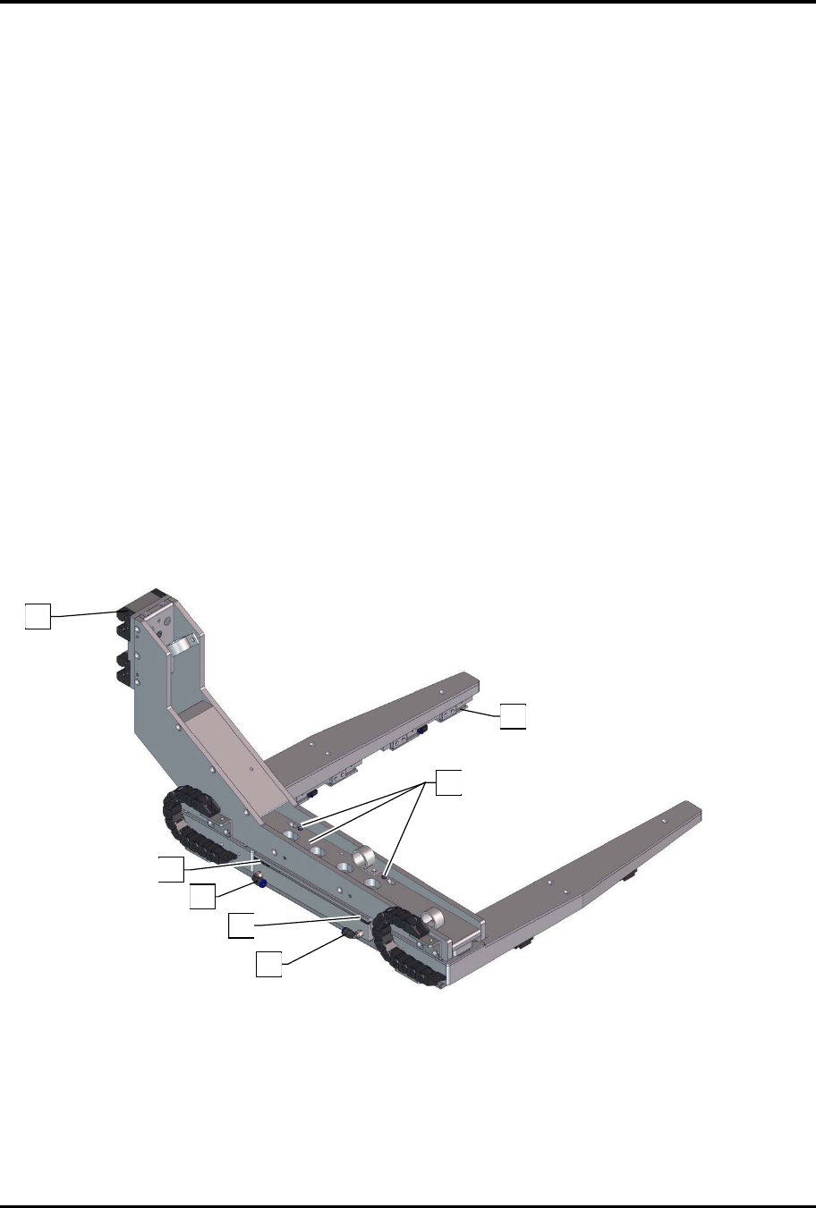
Figure 4-12 Gripper Assembly (Top View)
See Table 4-6 for callout descriptions.
9
2
5
4
5
4
3