FlexTRAK 2MB Material Handler Addendum Rev 05.pdf - 第38页
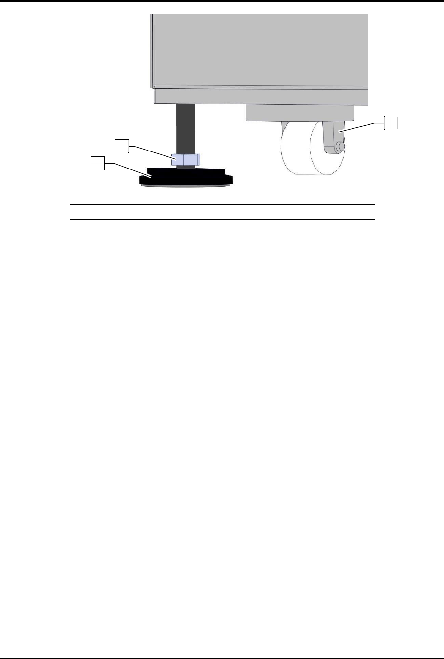
FlexTRAK Series 2MB Mater ial Handler Adden dum Installation 3-6 © 2023 Nordson Corporati on Item Description 1 Heigh t Adjustment Locking Nut (7/8 inch open-end wrench) 2 Leveler (Footpad) 3 Wheel Assembly Figure 3-2 Le…
FlexTRAK Series 2MB Material Handler Addendum Installation
© 2023 Nordson Corporation 3-5
3.5 Placing the System
Once the FlexTRAK-2MB has been unpacked, it must be moved to its location at the facility.
WARNING! Hazardous voltages are found within the lower enclosure of the
FlexTRAK-2MB System. Use extreme caution to prevent injury to personnel
or damage to equipment. Only qualified technicians should install this
equipment.
WARNING! Only qualified technicians should perform system installation. It
is recommended that at least two persons guide the system while it is being
positioned on the factory floor.
WARNING! When a chiller is hooked up to the FlexTRAK, a secondary
water containment system, such as a drip pan, should be installed underneath
the FlexTRAK in order to comply with SEMI-S2 safety guidelines. This
system should include leak detection and, if possible, should have a large
enough capacity to hold all of the water used in the cooling system.
To place the system in its factory location:
1. Carefully transport the system to the installation site using a forklift or floor jack.
?
NOTE To move the system short distances, you can use the wheels attached to the bottom of the
plasma system. Then raise or lower the levelers to the desired height using a wrench.
2. Once the system has been positioned in the desired location, slowly lower the forklift until
the chamber rails are approximately at the desired height.
3. Unscrew each leveler (footpad) until it touches the floor.
4. Lower and remove the forklift (Figure 3-2).
5. Place a level across the top of the system to make sure that it is level front-to-back and side-
to-side.
6. Use an open-end wrench to turn the height adjustment nut in the desired direction to raise or
lower the system to the correct position (Figure 3-2).
FlexTRAK Series 2MB Material Handler Addendum Installation
3-6 © 2023 Nordson Corporation
Item Description
1 Height Adjustment Locking Nut (7/8 inch open-end wrench)
2 Leveler (Footpad)
3 Wheel Assembly
Figure 3-2 Leveling the System
7. Align Lane 1 by sliding a workpiece from the upstream machine's conveyor to the
FlexTRAK-2MB conveyor and then from the FlexTRAK-2MB conveyor to the downstream
machine’s conveyor.
?
NOTE Use an open-end wrench to turn the height adjustment nut in the desired
direction to maintain levelness throughout the system.
8. Align Lane 2.
„ This is a teachable setting within the FlexTRAK-2MB system software.
„ Enter into the teach mode to align and teach this lane with the upstream and
downstream machines, see 3.7 Initial Start-up Procedure.
9. If desired, install seismic brackets on each leveler or use other methods to anchor the
system in place.
1
3
2
FlexTRAK Series 2MB Material Handler Addendum Installation
© 2023 Nordson Corporation 3-7
3.6 Connecting to the Facility
DANGER! Combining the process gas oxygen with hydrogen or forming gas
can cause fire or explosion. Ensure that these gases are not supplied to the
plasma system at the same time. Hydrogen should only be supplied by a low-
volume hydrogen generator.
WARNING! Appropriate lockable valves should be installed on inlets for gas
lines supplying hazardous gases or high-pressure nitrogen.
CAUTION! Certain process gases selected for use with this equipment may
be hazardous. Consult with your facilities safety officer to ensure proper
precautionary steps are taken before these gases are connected or used.
CAUTION! All process gas connections must be made with corrosion
resistant materials such as PTFE or stainless-steel tubing. Other materials may
corrode, clogging gas shut-off solenoids and mass flow controllers.
WARNING! When an optional chiller is hooked up to the FlexTRAK, a
lockable water valve should be installed on the water-in port.
To connect the material handler to the facility (Figure 3-3):
1. Using a 9/16-inch wrench or adjustable wrench, connect the gas/water cooling system
supply lines to the rear of the FlexTRAK-2MB System.
?
NOTE Connect the lines directly to the appropriate inlet connector or lockable valve,
as applicable.
„ Pressurized air supply line to the CDA inlet.
„ Chamber purge gas supply line (N
2
or CDA) to the PURGE inlet (Pump Purge option
only).
„ Vacuum Pump N
2
purge to the PUMP PURGE inlet.
„ Process gas supply lines to the GAS 1, GAS 2, GAS 3, and GAS 4 inlets. Water lines
to WATER IN and WATER OUT ports.
„ Chamber drain line(s) to a water containment system.
WARNING! Run the cooling system and check for any water leaks before
connecting the main power.
2. Attach a facility-compatible power plug to the main power cord.