FlexTRAK 2MB Material Handler Addendum Rev 05.pdf - 第12页
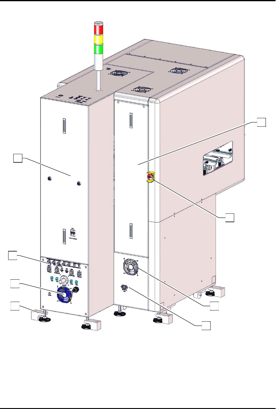
FlexTRAK Series 2MB Mater ial Handler Adden dum Introduction 1-4 © 2023 Nordson Corporati on Figure 1-2 Rear View Features 3 1 1 3 4 2 6 5

FlexTRAK Series 2MB Material Handler Addendum Introduction
© 2023 Nordson Corporation 1-3
Table 1-1 Front View Component Description
Item Name Description
1 Light Tower
The Light Tower is a device that displays system status and
can warn the operator when fault conditions exist.
2 Safety Cover Assembly
The Safety Cover Assembly allows access to the reaction
chamber and material handler components.
3
FlexTRAK DC Electronics
Enclosure
Refer to the FlexTRAK Installation, Operation, and
Maintenance Manual for description.
4 MHS Electrical Enclosure
The MHS Electrical Enclosure allows access to material
handler electrical components.
5 E-Stop Button
Pressing the E-Stop Button stops all system motion for both
the FlexTRAK and the Material Handling System. The E-Stop
Button does NOT completely turn off power to the
FlexTRAK-2MB system.
6 USB Connection Port Allows a USB device to be connected to the FlexTRAK-2MB.
7 ESD Wrist Strap Jack
ESD wrist straps worn by the operator plug into this jack to
prevent Electrostatic Discharge (ESD) damage to work
pieces during system operation.
8 ON Button
The green ON (l) button illuminates and switches ON power
to the system.
9
Emergency Machine Off (EMO)
Button
Pressing the EMO button completely turns off power to the
FlexTRAK-2MB System. When activated, the main power
connection to the system is disconnected via a momentary
action switch that sets the main power relay to the OFF state
and stops operation.
10 HMI PC Touch Screen
The FlexTRAK system is easy to operate using a Human-
Machine Interface (HMI) Touch Screen. During operation,
system information is displayed on the screen.
FlexTRAK Series 2MB Material Handler Addendum Introduction
1-4 © 2023 Nordson Corporation
Figure 1-2 Rear View Features
3
1
1
3
4
2
6
5

FlexTRAK Series 2MB Material Handler Addendum Introduction
© 2023 Nordson Corporation 1-5
Table 1-2 Rear View Feature Description
Item Name Description
1 Rear Access Panels
The Rear Access Panels allow access to system
components.
2 System Facilities Panel
The System Facilities Panel contains system facility
connection inputs, see 3.6 Connecting to the Facility.
3 Cooling Fans
The Cooling Fans regulate the temperature for system
components.
4
Seismic Feet (Optional)
The optional Seismic Feet can be used to level and secure
the system.
5 208V Power Connection
Power Connection for accessories (e.g., H
2
generator)
that will be turned off when the system is shut down.
6
Rear Emergency Machine Off
(EMO) Button
Pressing the rear EMO button completely turns off power
to the FlexTRAK-2MB system. When activated, the main
power connection to the system is disconnected via a
momentary action switch that sets the main power relay
to the OFF state and stops operation.