Spectrum+Operating+Manual.pdf - 第106页
S2-9 XX X Se ri es Disp ensi n g Syst em IOM Man ual Calibration and Adjus tment 5-30 © 2023 Nordson Corporatio n 9. C lick on OK t o c lose the Heater Control W indow. 10. Click o n Main t o re tu rn to the Fluidm ove M…
S2-9XXX Series Dispensing System IOM Manual Calibration and Adjustment
© 2023 Nordson Corporation 5-29
To configure CpH:
NOTE CpH can be added to any station and each station is configured independently.
1. In the Fluidmove Main window, select
Tools > Terminal.
2. Select
Heater 2 (Conveyor 1) or Heater 3 (Conveyor 2).
The Heater Control Window opens (Figure 5-30).
3. Double click on the station that you want to configure.
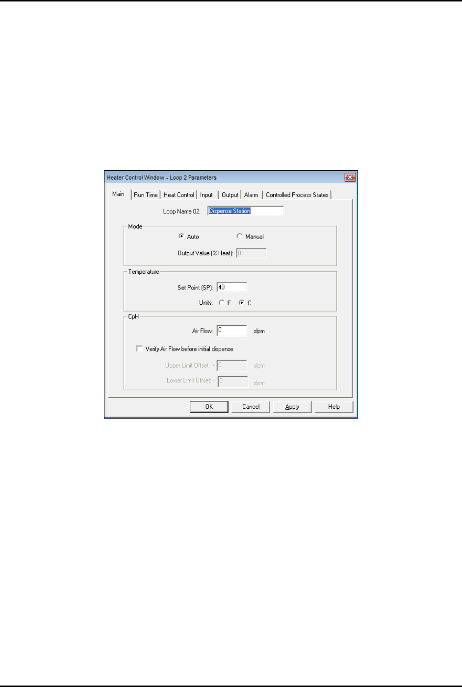
The Heater Control Loop Parameters Window opens (Figure 5-35).
Figure 5-31 Heater Control Loop Parameters Window - Main Tab
4. Enter the desired settings on the Main tab.
5. If you want to set ramp and standby options, go to Step 6, otherwise skip to Step 9.
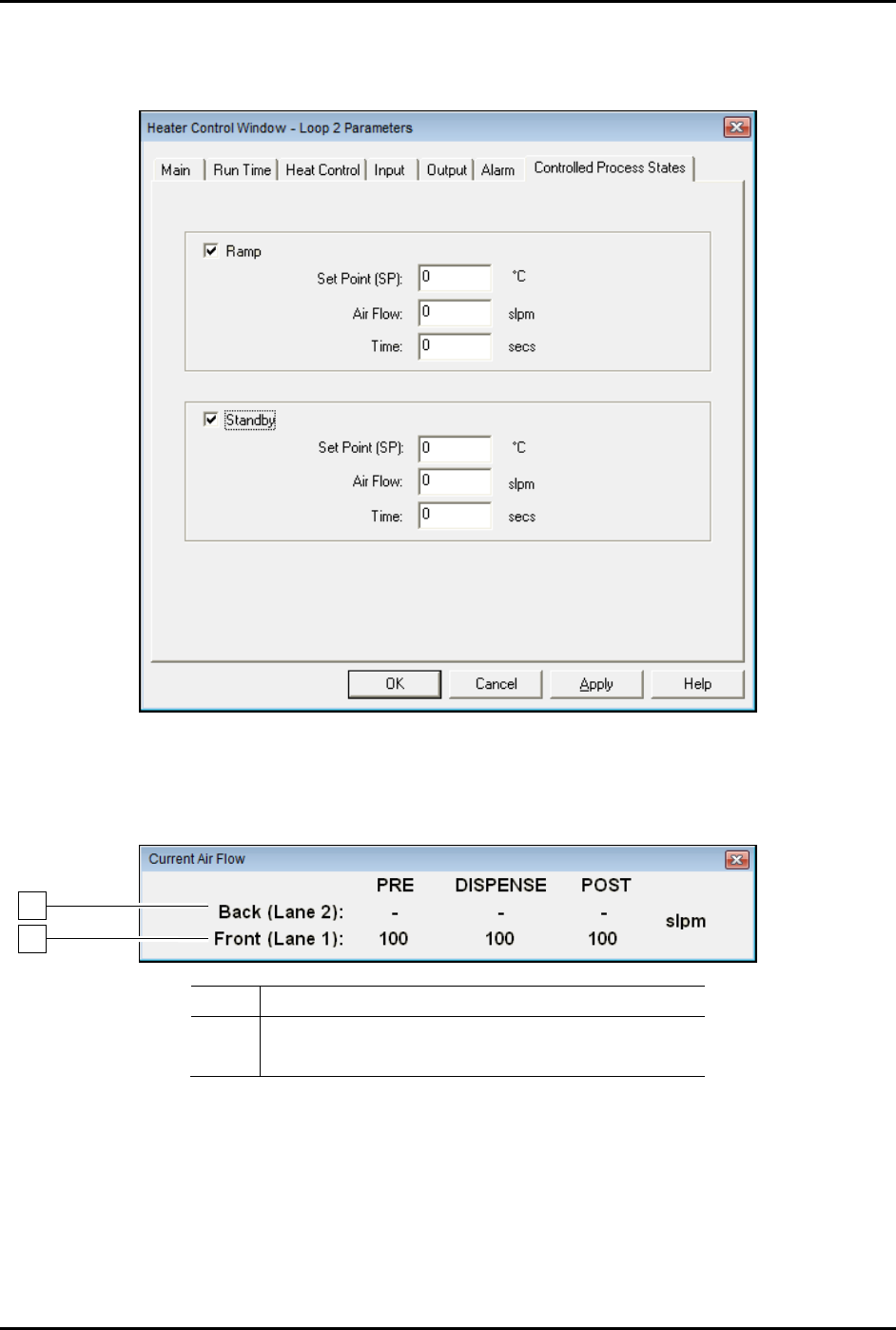
6. Click on the Controlled Process States tab (Figure 5-36).
7. Enter the desired ramp temperature, airflow, and time.
The ramp temperature is generally higher than the dispense station temperature and is
used to quickly heat a part in the pre-dispense station.
8. Enter the desired standby temperature, airflow, and time.
The standby temperature is generally lower than the dispense station temperature and is
used to reduce energy when a board is not received for a specified amount of time.
S2-9XXX Series Dispensing System IOM Manual Calibration and Adjustment
5-30 © 2023 Nordson Corporation
9. Click on OK to close the Heater Control Window.
10. Click on
Main to return to the Fluidmove Main Window.
Figure 5-32 Heater Control Window - Controlled Process States
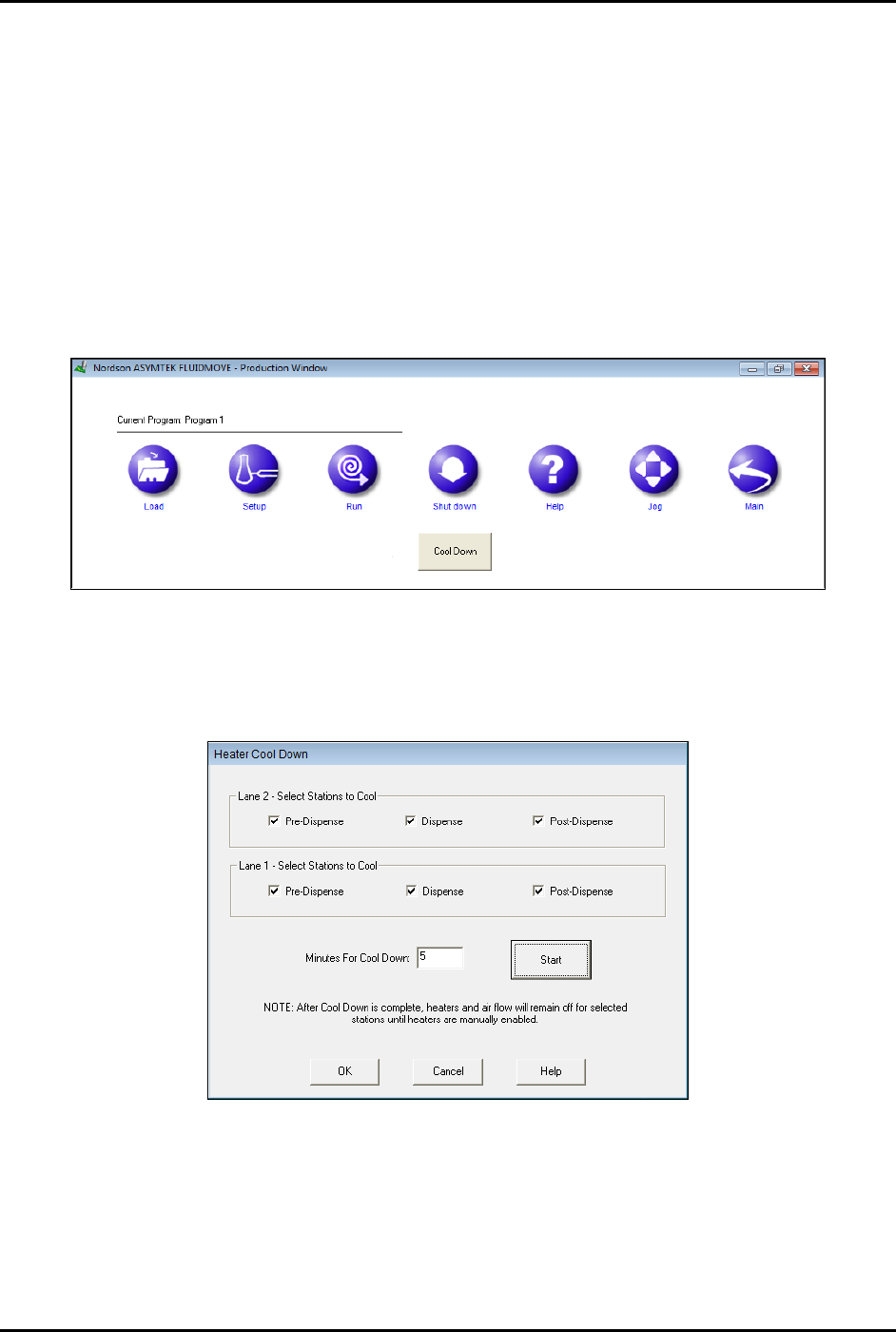
11. You may press [Ctrl + A] in any Fluidmove window to toggle the Current Air Flow toolbar
ON and OFF (Figure 5-37).
Item
Description
1
Conveyor 1 Impingement Airflow
2 Conveyor 2 Impingement Airflow
Figure 5-33 Current Air Flow Toolbar
1
2
S2-9XXX Series Dispensing System IOM Manual Calibration and Adjustment
© 2023 Nordson Corporation 5-31
5.15.2 CpH Cool Down
The cool down feature will allow the operator to select which stations should be cooled down before
working on or removing a heater module. The heater will be shut off and maximum air flow will be
applied for a given amount of time specified by the operator.
To cool down the heaters:
1. In the Fluidmove Main window, click on
Run a Program.
The Production Window opens.
2. Click on
Shutdown.
The Cool Down button appears (Figure 5-38).
Figure 5-34 Fluidmove Main Window - Cool Down Button
3. Click on Cool Down.
The Heater Cool Down window opens (Figure 5-39).
Figure 5-35 Heater Cool Down Window
4. Select the desired stations and enter a cool down time.
5. Click
Start to begin the cooling process.
6. Click on
Cancel to stop the cooling process before the time expires.