Spectrum+Operating+Manual.pdf - 第139页
© 2023 Nordson C orporation 7-1 7 Tr ou blesho oting 7.1 Overvi e w If you have di ffi culty o pe r ating yo ur dispe n sing system , use this section to id entify a possible so lution to the probl em . If you have diffi…
S2-9XXX Series Dispensing System IOM Manual Maintenance
6-26 © 2023 Nordson Corporation
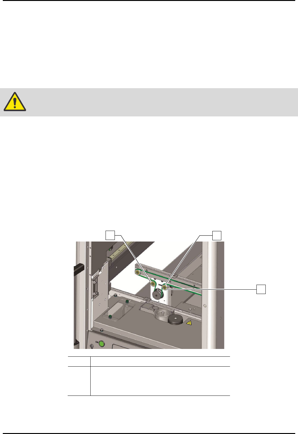
6.13 Tensioning the Conveyor Belts
To tension the conveyor belts (Figure 6-18):
1. Perform a service shutdown, see 2.14 Service Shutdown.
2. If applicable, lift the heater tooling assembly out the dispense station to provide access to
the conveyor belt adjustment pulley.
There is a belt adjustment pulley for each belt.
WARNING! Make sure the heater tooling is cool before removal.
3. Loosen, do not remove, the belt tensioner screw located on the belt adjustment pulley.
Hold the bolt on the back of the belt adjustment pulley while loosening the screw so
that it will not turn with the screw.
4. Move belt tension pulley right and left until the desired tension is obtained.
5. Tighten the belt tensioner screw.
6. Torque the belt tensioner screw to 9.8 Nm (87 in-lbs).
7. Repeat Step 3 through Step 6 for the other conveyor belt.
8. If the dispensing system is equipped with dual conveyors, perform Step 3 through Step 6 for
the other conveyor.
Item Description
1
Conveyor Belt
2 Belt Adjustment Pulley
3
Belt Tensioner Screw
Figure 6-18 Tensioning the Conveyor Belts
NOTE If the conveyor belts need to be replaced, see 8.12 Replacing the Conveyer Belts.
3
1
2
© 2023 Nordson Corporation 7-1
7 Troubleshooting
7.1 Overview
If you have difficulty operating your dispensing system, use this section to identify a possible solution to
the problem. If you have difficulties not listed in this section, or the suggested solution does not correct
the problem, contact Asymtek Technical Support.
NOTE There are no user serviceable parts inside the electrical modules. Refer to the Fluidmove
User Guide or Fluidmove Online Help for assistance with the Fluidmove software.
7.2 Safety First
Operation of your dispensing system involves heat, air pressure, electrical power, mechanical devices,
and the use of hazardous materials. Read this manual in its entirety before attempting any system or
component operation. It is essential for all personnel working on or around the dispensing system to fully
understand the hazards, risks, and safety precautions associated with operating the system. When properly
operated and maintained, the dispensing system is safe and reliable. See Section 2 - Safety for additional
information.
WARNING! Allow only qualified personnel to perform system troubleshooting. Observe and
follow the safety instructions in this document and all other related
documentation. Failure to do so may cause serious bodily injury to the user or
damage to the equipment.
WARNING! DO NOT hot swap connections when working with electrical and pneumatic
power supplies. Turn the main circuit break off before disconnecting the external
power plug from the facility.
7.3 Record Keeping
The type of procedure performed should be recorded in maintenance records for the dispensing system.
Dates, part numbers/serial numbers of replaced parts, names of technicians, and other pertinent data
should be recorded.

S2-9XXX Series Dispensing System IOM Manual Troubleshooting
7-2 © 2023 Nordson Corporation
7.4 Basic System Troubleshooting
7.4.1 System Power
Table 7-1 System Power Troubleshooting
Symptom Possible Cause Recovery Procedures
No power to major
system components
The ON (l) button has not been
pressed.
Press ON (l) on the front panel. The green
button illuminates green as an indicator the
machine is on.
A circuit breaker has been tripped.
The dispensing system incorporates circuit
breakers with a “push to reset” feature rather
than fuses. There are also branch circuit
breakers which could cause the laptop to lose
AC power and/or the 48V servo power supply
to lose power. For detailed troubleshooting of
power related issues, contact Asymtek
Technical Support.
A branch circuit breaker in one of
the conveyor modules has been
tripped.
Main power cable is disconnected.
Check that the main power cable is connected
to an AC source.
Main power circuit breaker turned
OFF.
Turn ON the main power circuit breaker at the
rear of the system. The sub-systems receive
electrical power entirely through the power
manager, accessible from the rear of the
machine. The main circuit breaker switch is the
only mechanism for completely powering down
the system, including power to the laptop.
EMO button has been activated.
1. Turn all EMO buttons clockwise until they
pop out. The EMO buttons at the front and
rear of the system interrupt power to all
power connections except the laptop
computer, light beacon and camera.
2. Press
ON
(
l
) on the front panel.
Interlock circuit is interrupted.
Make sure the dispensing area door is closed.
The interlock places the servo control system
in a low power state that is just sufficient to
hold the positioner in place for syringe
changes. Opening the dispensing area door
does not completely power down the
dispensing system and does not power off the
laptop.
Ventilation Time Delay (Flux
Applications).
The dispensing system turns on after an
approximate 60-second vent air time delay.
A fuse on the Main PWA may have
blown.
Replace fuse, see 8.16 Replacing Fuses.
System fails to start
Power controls cable disconnected.
Verify the power controls cables are properly
routed and connected from the power
manager to the front panel switches.
Button failure. Contact Asymtek Technical Support.
Safety Interlock fails to
reset
Interlock activated.
Make sure the hood is closed. If the interlock
still fails to reset, contact Asymtek Technical
Support.