Spectrum+Operating+Manual.pdf - 第58页
S2-9 XX X Se ri es Disp ensi n g Syst em IOM Man ual Installation 3-6 © 2023 Nordson Corporatio n 3.7 Levelin g the Dispensing System WARNIN G! This pr oc edure s hould only be pe rformed by a tr ained se rvi c e technic…
S2-9XXX Series Dispensing System IOM Manual Installation
© 2023 Nordson Corporation 3-5
Figure 3-3 Removing the Front Cover
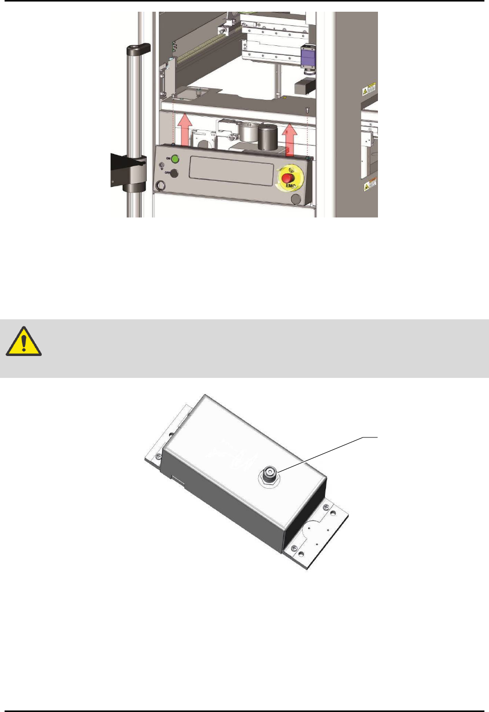
9. If the system is equipped with a scale, loosen the strap covering the scale and remove the
warning tag from the scale unit.
NOTE Do not remove the strap. The strap may be needed when moving or shipping
machine.
CAUTION! The scale stem is extremely sensitive. Be careful not to hit or apply pressure to
the scale stem (Figure 3-4).
Figure 3-4 Scale Stem
10. Replace the scale cover and reinstall the two mounting screws.
NOTE It is not necessary to level the scale. The scale is leveled to the dispense plane at the
factory and does not need to be leveled again. However, it does need to be recalibrated
after the machine installation is complete, see 5.6 Calibrating the Scale.
11. Remove the tie wraps and warning tag from the lift table(s), if installed.
Scale Stem
S2-9XXX Series Dispensing System IOM Manual Installation
3-6 © 2023 Nordson Corporation
3.7 Leveling the Dispensing System
WARNING! This procedure should only be performed by a trained service technician.
To level the dispensing system:
1. Perform a service shutdown, see 2.14 Service Shutdown.
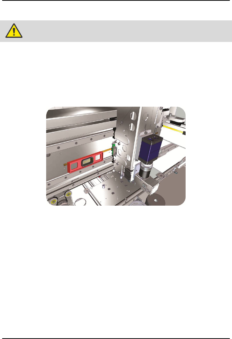
2. Place the box level on the X-axis linear guide (Figure 3-5).
3. Observe the position of the bubble within the level’s window.
The bubble should be centered, indicating the dispensing system is level from
side-to-side.
Figure 3-5 Leveling the X-Axis
4. If necessary, adjust the levelers (Figure 3-2) of the dispensing system as follows:
a. Loosen the 1 1/2-inch lock nut on the leveler.
b. Turn the 1 1/2-inch post nut in the desired direction until the level’s bubble is centered,
indicating that the system is level from side-to-side.
Turning the post nut clockwise raises the dispensing system. Turning the post nut
counterclockwise lowers the dispensing system.
c. Tighten the 1 1/2-inch lock nut on the leveler.
S2-9XXX Series Dispensing System IOM Manual Installation
© 2023 Nordson Corporation 3-7
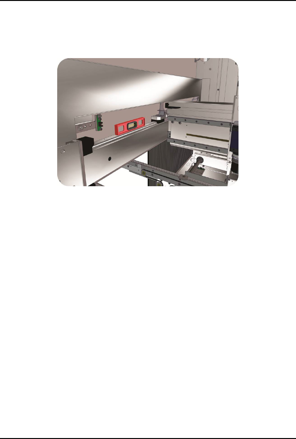
5. Place the box level along the Y-axis linear guide (Figure 3-6).
6. Observe the position of the bubble within the level’s window.
The bubble should be centered, indicating dispensing system is level from
front-to-back.
Figure 3-6 Leveling the Y-Axis
7. If necessary, adjust the levelers (Figure 3-2) of the dispensing system as follows:
a. Loosen the 1 1/2-inch lock nut on the leveler.
b. Turn the 1 1/2-inch post nut in the desired direction until the level’s bubble is centered,
indicating that the system is level from front-to-back.
Turning the post nut clockwise raises the dispensing system. Turning the post nut
counterclockwise lowers the dispensing system.
c. Tighten the 1 1/2-inch lock nut on the leveler.
8. Check the system for stability by putting your hands on top of the dispensing system in
one corner and pressing down. If one leveler is lower or higher than the others, the
dispensing system will rock back and forth. Adjust the levelers so that they are all bearing
the weight equally.
9. Re-level the dispensing system from side-to-side and from front-to-back, if necessary.