Spectrum+Operating+Manual.pdf - 第65页
S2-9 XXX Se ri es Dispensing Sys te m IOM Man ual Installation © 2023 Nordson Co rporat ion 3-13 3.11 Anchorin g the Di spensi n g Syst em To p revent movemen t th at coul d ca use injury to pe rsonnel a nd damage t o th…
S2-9XXX Series Dispensing System IOM Manual Installation
3-12 © 2023 Nordson Corporation
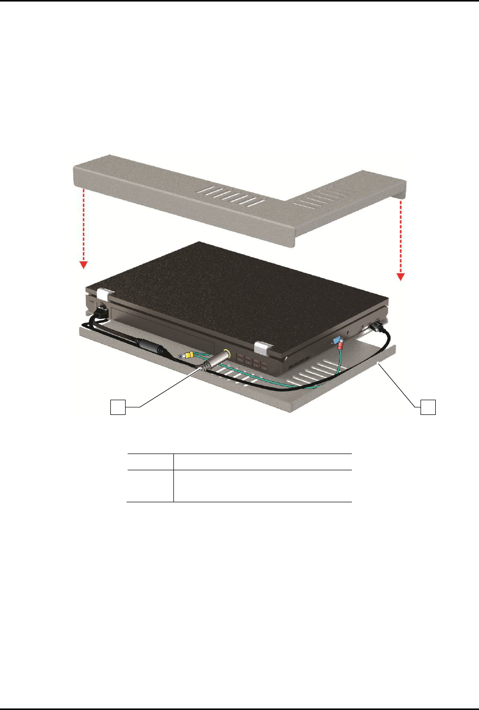
9. Attach the power cable to the rear of the computer.
NOTE The laptop is adhered to the tray with a hook and loop fastener. Align the laptop
computer before placing it on the tray.
10. With the laptop lid closed, align the computer with the covers so that no gaps exist on the
left side or the back edge.
11. Gently press the laptop onto the base.
12. Attach the locking cable to the laptop.
Item
Description
1 Power Cable
2
Laptop Tray
Figure 3-11 Aligning the Laptop Computer to the Tray
2
1
S2-9XXX Series Dispensing System IOM Manual Installation
© 2023 Nordson Corporation 3-13
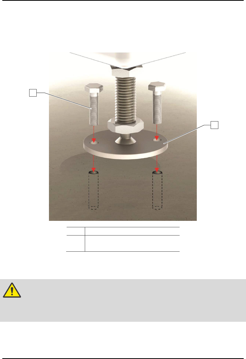
3.11 Anchoring the Dispensing System
To prevent movement that could cause injury to personnel and damage to the dispensing system and
facility, each dispensing system leveler (foot) should be anchored to the floor with two bolts
(Figure 3-12). The anchor joint (the point between each anchor bolt and the floor) must be able to
withstand at least 100 kg (220 lbs) of pullout force. For additional information, see 9.5 Stability Analysis.
Item
Description
1
Bolt
2 Leveler (Foot)
Figure 3-12 Anchoring the Dispensing System
NOTE You may also use the shipping brackets to anchor the dispensing system.
WARNING! The dispensing system is designed to be used as an inline system. When using
the dispensing system for batch operations, make sure it is configured with the
optional conveyor closeout kit (Item 38) to prevent personal injury and
equipment/workpiece damage.
2
1
S2-9XXX Series Dispensing System IOM Manual Installation
3-14 © 2023 Nordson Corporation
3.12 Installing the Dovetail Bracket
Tools and Materials Needed:
• Metric Allen Wrench Set
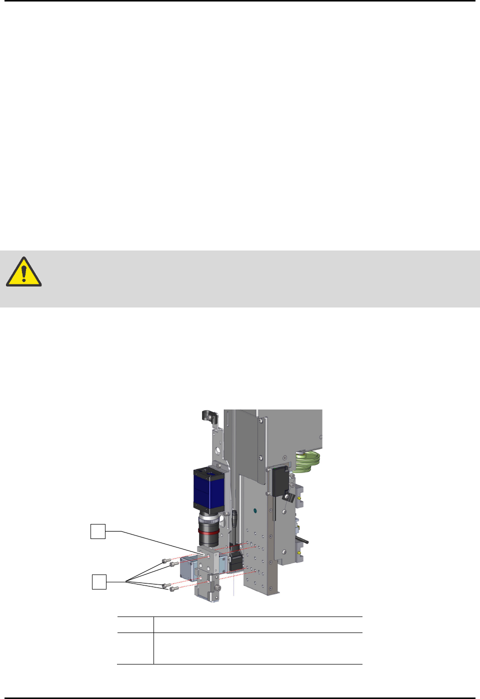
To install the dovetail bracket (Figure 3-13):
1. If power is on, perform a service shutdown, see 2.14 Service Shutdown.
2. Open the front hatch of the dispensing system.
3. Manually move the dispense head to the front of the dispensing system.
4. Align the four (4) screws of the dovetail bracket to the slots on the Z-head.
5. Ensure there are no gaps between the dovetail bracket and Z-head and adjust the position of
the dovetail bracket until flush with the Z-head.
6. Tighten the four (4) screws securing the dovetail bracket to the Z-head.
WARNING! Before tightening the screws, verify the dovetail bracket is flush and level with
the Z-head and with no gaps between them, or damage may occur.
7. Torque the four (4) screws to 5.64 Nm (50 in-lbs).
8. Repeat Step 4 through Step 7 for installing the dovetail bracket on the second Z-head.
9. Refer to the applicable applicator(s) manual for installation, configuration, and operation of
the applicator and the Fluidmove User Guide or Fluidmove Online Help for software
configuration instructions.
Item
Description
1 Screws (4)
2
Dovetail Bracket
Figure 3-13 Installing the Dovetail Bracket
2
1