Spectrum+Operating+Manual.pdf - 第110页
S2-9 XX X Se ri es Disp ensi n g Syst em IOM Man ual Calibration and Adjus tment 5-34 © 2023 Nordson Corporatio n 5.17 Adjusting the Li ft Table Speed To adjust the lift t able spe ed: 1. From the Flu id mo ve Main Menu …
S2-9XXX Series Dispensing System IOM Manual Calibration and Adjustment
© 2023 Nordson Corporation 5-33
Item
Description
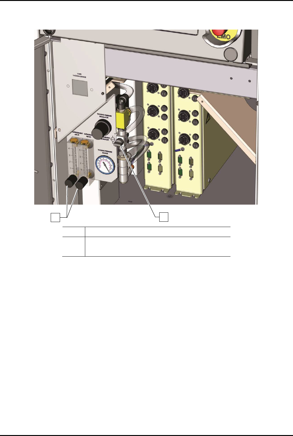
1 Flowmeter Adjustment Knobs
2
Impingement Air Valve
Figure 5-36 Adjusting the Impingement Heater Airflow (S2-9XXP Dual Conveyor)
1
2
S2-9XXX Series Dispensing System IOM Manual Calibration and Adjustment
5-34 © 2023 Nordson Corporation
5.17 Adjusting the Lift Table Speed
To adjust the lift table speed:
1. From the Fluidmove Main Menu, select
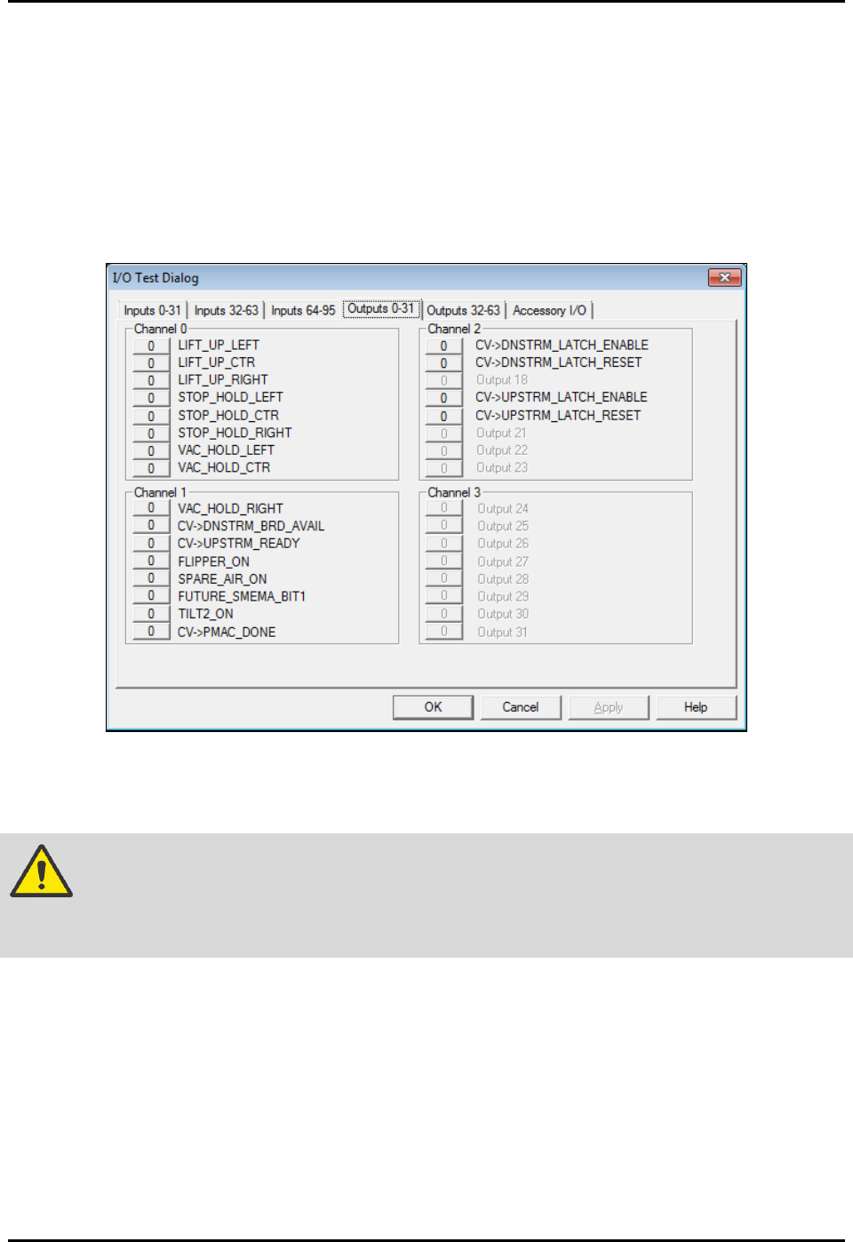
Configuration > Conveyor Setup > Test I/O.
2. Select the tab labeled “Outputs 0-31” and locate the lift output buttons (Figure 5-41) for the
station to be adjusted (Lift_Up_Left, Lift_Up_Ctr, Lift_Up_Right).
3. Toggle the lift output buttons On (1) and Off (0) to lift and lower the table to test the speed
adjustment setting.
Figure 5-37 Conveyor I/O Test Dialog
4. If adjustment is necessary, open the dispensing area door.
WARNING! Do not reach into the dispensing chamber until yellow beacon light is displayed
and all system motion has stopped. If the heaters are hot, use extreme caution
when performing this operation.
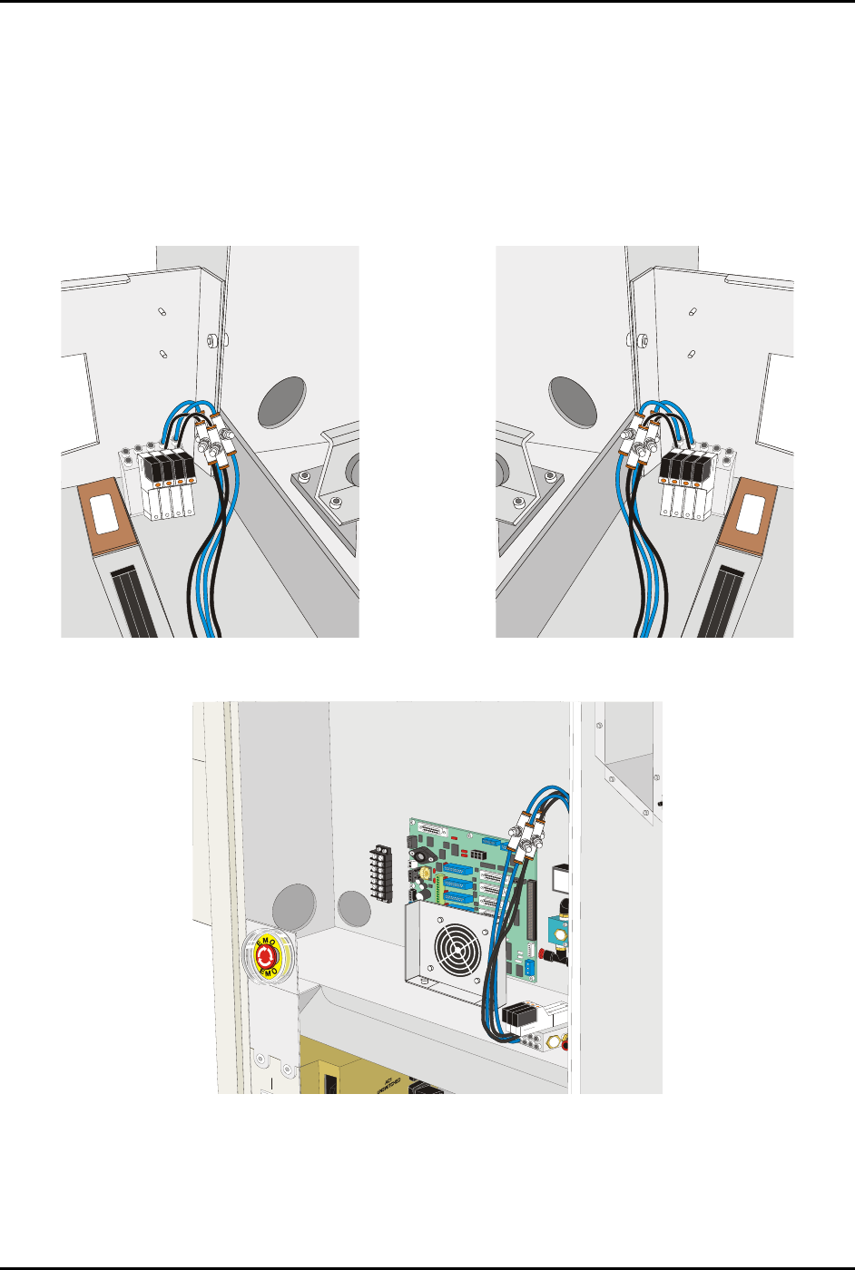
5. Locate the Flow Control Valves (FCVs) for the appropriate lift table.
NOTE Flow control valve locations are shown in Figure 5-42 through Figure 5-44. If
the system has dispense heat only, the FCVs are located under the lift table. To
gain access to the FCVs, it may be necessary to move the dispensing head to
the rear of the machine.
S2-9XXX Series Dispensing System IOM Manual Calibration and Adjustment
© 2023 Nordson Corporation 5-35
6. Adjust the FCVs as follows:
a. Adjust FCVs with the black hose for upward speed.
b. Adjust FCVs with the blue hose for downward speed.
7. Close the dispensing area door and toggle the lift output buttons to test the speed.
8. Repeat Step 6 and Step 7 until you are satisfied with the lift table operation.
9. When done, exit conveyor setup and return to the Fluidmove Main window.
Figure 5-38 Pre-Dispense Lift Table Controls
Figure 5-39 Post-Dispense Lift Table Controls
Figure 5-40 Dispense Lift Table Controls