Spectrum+Operating+Manual.pdf - 第161页
S2-9 XXX Se ri es Dispensing Sys te m IOM Man ual Parts Replacement © 2023 Nordson C orpor ation 8-9 To install the scale assembly: 1. Install the scale assembly to the dispensing system with fou r (4) screws ( Figure 8-…
S2-9XXX Series Dispensing System IOM Manual Parts Replacement
8-8 © 2023 Nordson Corporation
Item
Description
Item
Description
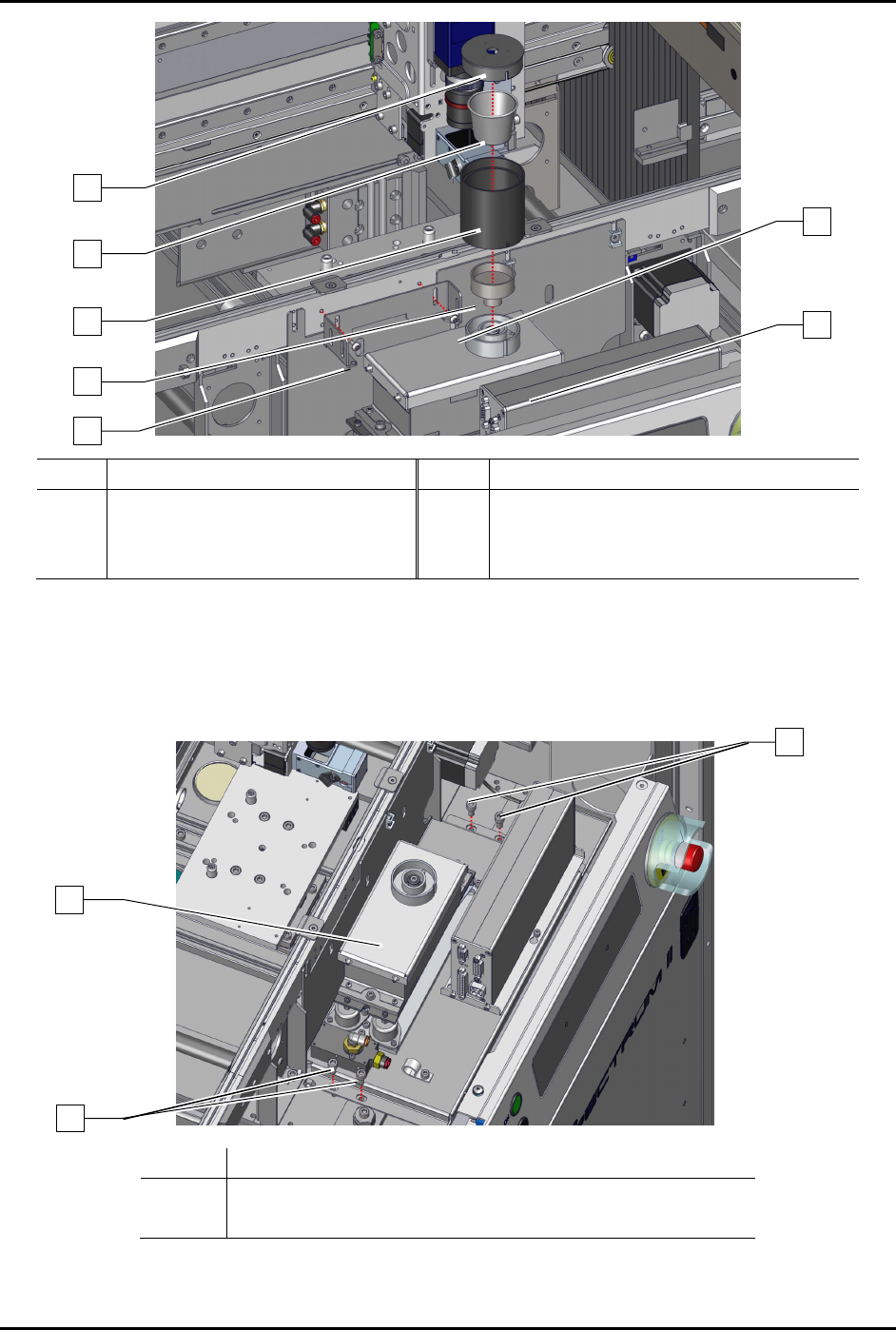
1 Scale Lid 4 Scale Pedestal
2 Scale Cup 5 Screws (2)
3 Breeze Shield 6 Service Station Bracket
Figure 8-4 Replacing the Scale Components and Service Station Bracket
10. Remove the four (4) screws securing the scale assembly to the dispensing system
(Figure 8-5).
11. Remove the scale assembly from the dispensing system.
Item
Description
1 Kit, FRU, S2-9XX Scale Assy (Item 30)
2 Screws (4)
Figure 8-5 Replacing the Scale Assembly
6
5
2
3
4
5
1
1
2
2
S2-9XXX Series Dispensing System IOM Manual Parts Replacement
© 2023 Nordson Corporation 8-9
To install the scale assembly:
1. Install the scale assembly to the dispensing system with four (4) screws (Figure 8-5).
2. Torque the four (4) screws to 9.8 Nm (87 in-lbs).
3. Install the scale pedestal, breeze shield cover, scale cup, and scale lid onto the scale
assembly (Figure 8-4).
4. Install the two (2) screws securing the valve bracket to the rail.
5. Place a bubble level on top of the scale lid.
6. Loosen, do
not remove, the three (3) securing screws (Figure 8-6).
7. Adjust the three (3) leveling screws to level the scale assembly.
The scale lid should be flush or 2 mm above the conveyor rail.
8. Tighten the three (3) securing screws securing the scale assembly while ensuring the scale
remains level.
9. Remove the bubble level from the top of the scale lid.
10. If a scale shutter is installed, connect the pneumatic connect
ions to the scale assembly.
11. Connect the electrical connection to the scale assembly.
12. Install the service station, see 8.9.1 Replacing the Service Station.
13. Close the dispensing area door.
Item
Description
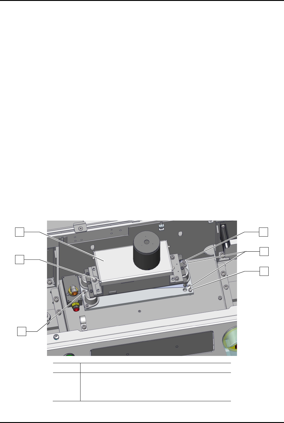
1 Kit, FRU, S2-9XX Scale Assy (Item 30)
2 Leveling Screws (3)
3 Securing Screws (3)
Figure 8-6 Leveling the Scale Assembly
1
3
3
2
3
2

S2-9XXX Series Dispensing System IOM Manual Parts Replacement
8-10 © 2023 Nordson Corporation
8.12 Replacing the Camera Lens and Mechanical/Tactical
Height Sensor
Tools and Materials Needed:
• Hex Wrench (Item 59)
WARNING! Except for lens replacement and lighting adjustments, all other configuration and
adjustments should only be performed by a trained service technician.
8.12.1 Replacing the Camera Lens
To remove and replace the camera lens:
1. Perform a service shutdown, see 2.14 Service Shutdown.
2. Open the dispensing area door.
3. Loosen but do not remove the three (3) screws securing the camera to the bracket
(Figure 8-7).
4. Slide the camera assembly to the top of the bracket.
5. Secure the camera to the bracket by tightening three (3) screws.
6. Remove the lower, middle, and upper section as an assembly from the 2x optical lens by
turning counterclockwise.
NOTE Do not remove the 2x optical lens.