Spectrum+Operating+Manual.pdf - 第23页
S2-9 XXX Se ri es Dispensing Sys te m IOM Man ual Introduction © 2023 Nordson Co rporat ion 1-13 1.9.3 Service Station It em Name Description 1 Dispense Tile The D isp ens e T ile is a ceram i c ti le d ispensed upon dur…
S2-9XXX Series Dispensing System IOM Manual Introduction
1-12 © 2023 Nordson Corporation
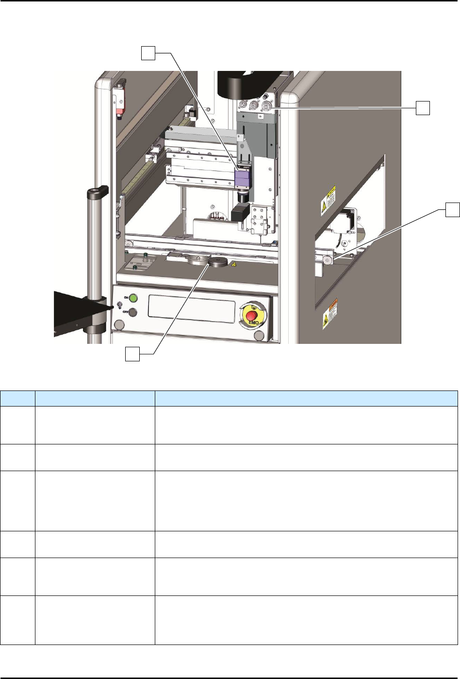
1.9.2 Dispensing Area
Item
Name
Description
1 Vision System
The compact, high resolution, black and white camera and lens are
part of the Vision System. They are mounted on the dispensing head
and are used to view work surfaces.
2
Pneumatic and Electrical
Connections
The bulkhead includes valve, low fluid sensor, and air pressure
connections.
3 Conveyor
The Conveyor transports the workpiece from an upstream system to
the dispensing station and then to a downstream system. All
Conveyors are SMEMA compatible and have adjustable rear rail
width. A Dual Lane Conveyor configuration that allows parallel
processing on two lanes for continuous dispensing is also available.
4 Service Station
The Service Station consists of the dispense tile, tactile needle
sensor, purge station, and scale (Figure 1-5).
Dispensing Valve
(NOT SHOWN)
The Dispensing Valve controls or regulates the flow of material from
a pressurized reservoir, such as a syringe. Devices include valves
and jets.
Laser Height Sensor
(NOT SHOWN)
The Laser Height Sensor is a device that measures substrate height
and sends a signal to the system computer. The height information
is
used to position the dispensing needle at an exact distance above
the workpiece surface.
Figure 1-5 Dispensing Area
2
1
3
4
S2-9XXX Series Dispensing System IOM Manual Introduction
© 2023 Nordson Corporation 1-13
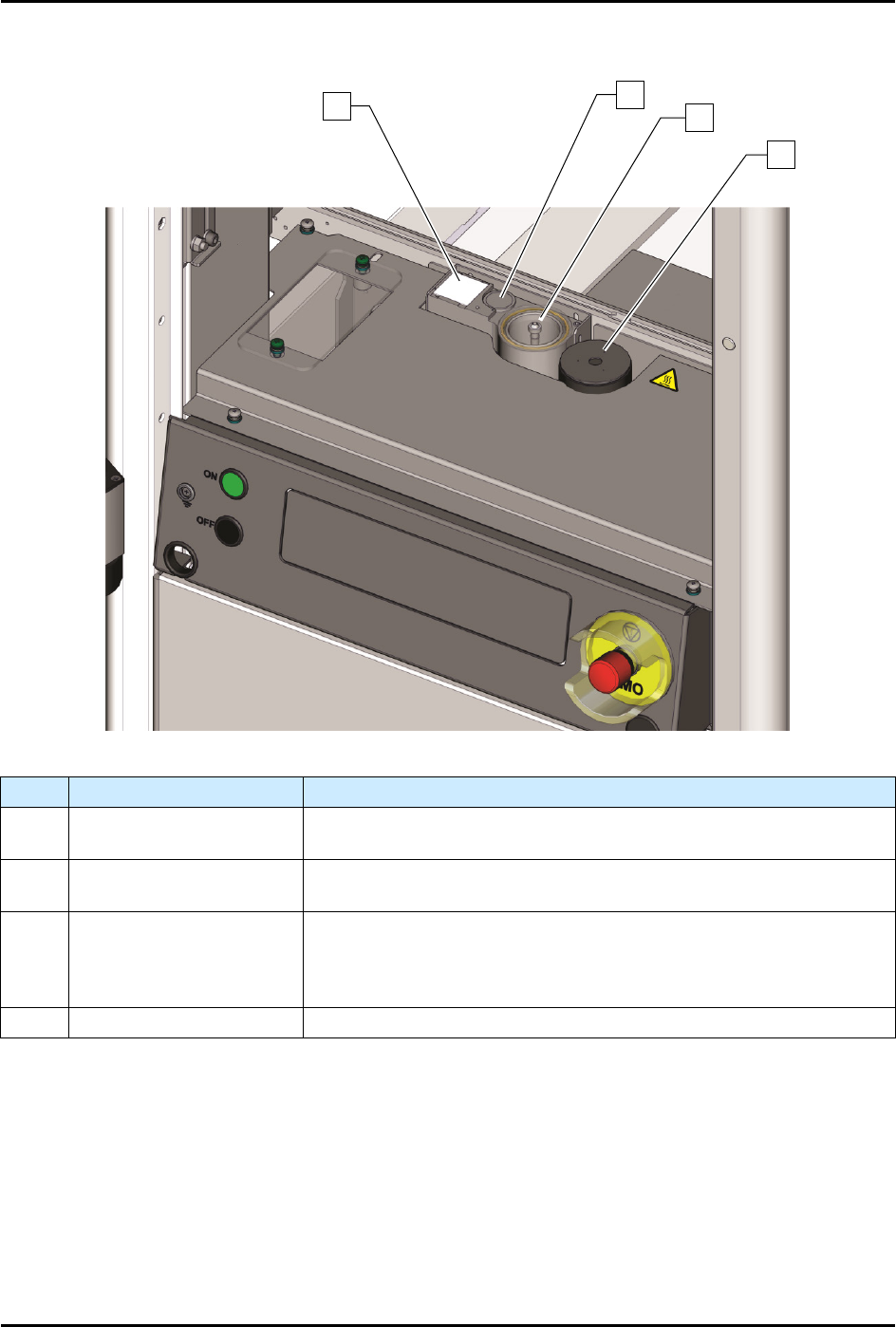
1.9.3 Service Station
Item
Name
Description
1 Dispense Tile
The Dispense Tile is a ceramic tile dispensed upon during system
offset routines.
2 Tactile Needle Sensor
The Tactile Needle Sensor measures the offset between the
needle/nozzle and the height sensor.
3 Purge Station
The Purge Station consists of a small reservoir that contains a
disposable plastic cup and is attached to a vacuum generator. Air
flowing through the purge boot into the cup removes excess fluid on
the dispensing valve needle/nozzle.
4 Scale See 1.11.4 Scale.
Figure 1-6 Service Station
1
2
3
4
S2-9XXX Series Dispensing System IOM Manual Introduction
1-14 © 2023 Nordson Corporation
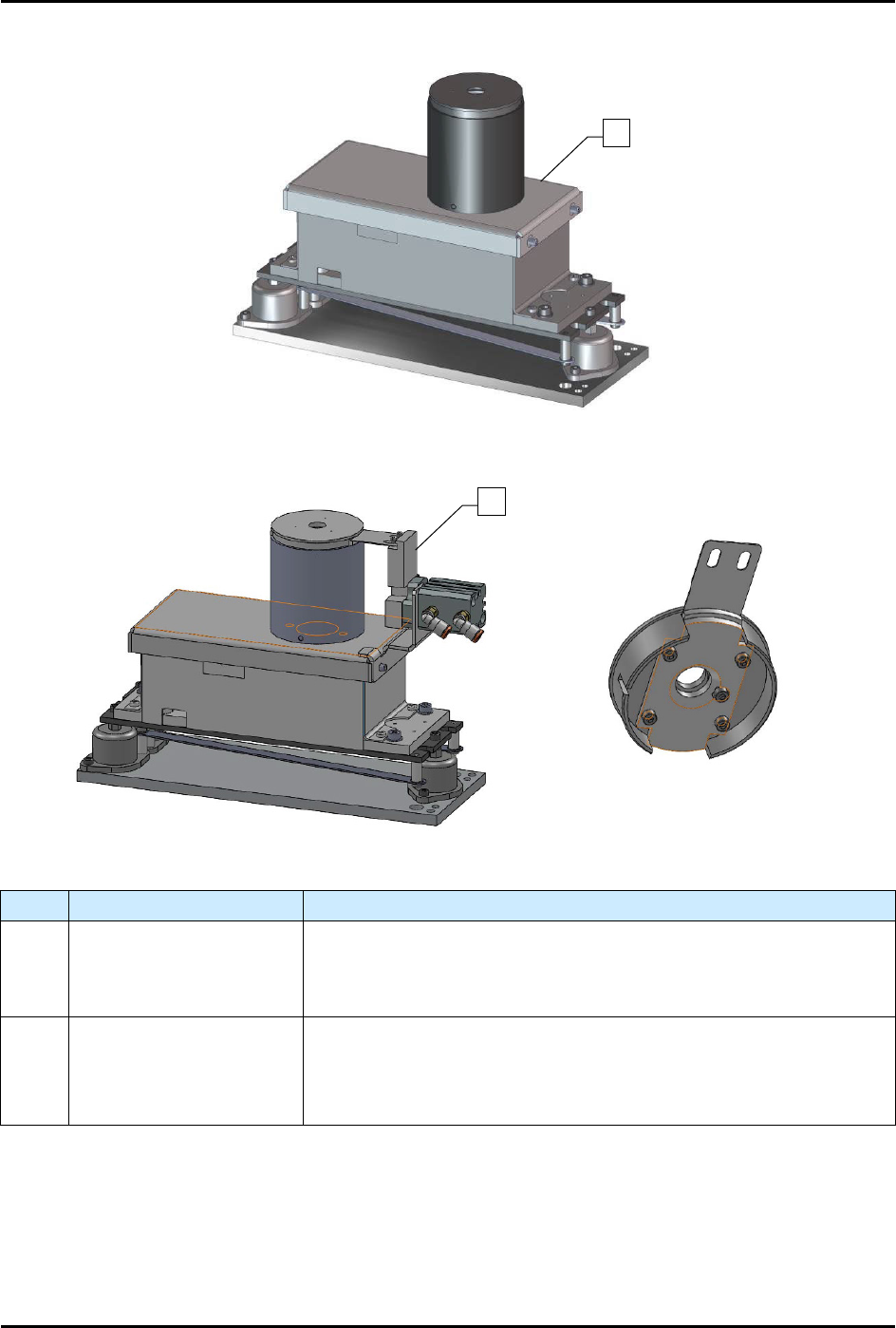
1.9.4 Scale
Scale Assembly
Scale Assembly with Shutter (Cleanroom)
Item
Name
Description
1 Scale Assembly
The scale measures the weight of dispensed fluid and sends the
information to the Fluidmove software for mass flow calibration. The
scale is standard on S2-9XXP systems and an option on S2-9XXX
systems.
2
Scale Assembly with
Shutter (Cleanroom)
The S2-9XXX
Cleanroom configuration has a pneumatically actuated
shutter mechanism built into the scale to prevent fluctuations due to
the ULPA filter System. The shutter only opens when dispensing into
the scale.
Figure 1-7 Scale Assembly
1
2