Spectrum+Operating+Manual.pdf - 第73页
S2-9 XXX Se ri es Dispensing Sys te m IOM Man ual Operation © 2023 Nordson Co rporat ion 4-3 4.5 Came ra States T he dispensing system feat ures a Da l sa Genie M640 digital 640 x 480 pi xel camer a. The camera communica…
S2-9XXX Series Dispensing System IOM Manual Operation
4-2 © 2023 Nordson Corporation
For machines equipped with a vent air switch (machines that require vent air), system
power-up is delayed by 60 seconds after the ON button is pushed. The 60 second delay is to
provide enough time to exhaust the work-cell from any flammable or explosive vapors.
It may take several minutes for the camera to acquire a connection with the laptop
computer. DO NOT attempt to run Fluidmove or DALSA programs during this time.
A blue camera icon with a red X crossing it will be displayed on the Windows taskbar.
After the camera is connected, the red X disappears and a message pops up stating that
the “device has limited or no functionality.” This is normal and means that you cannot
connect to the Internet with this device
.
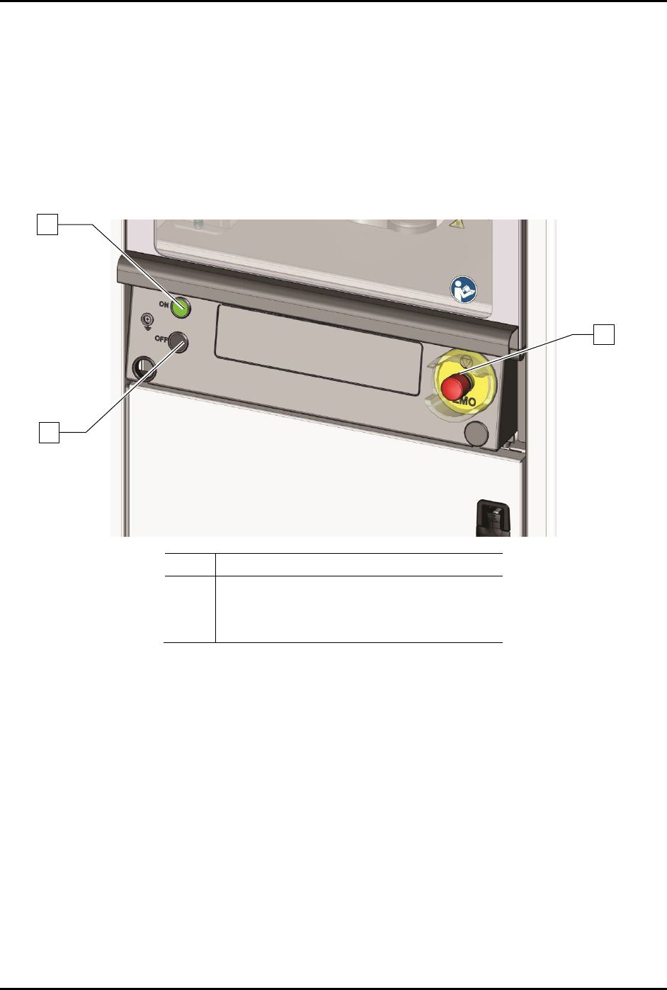
Item
Description
1 On Button
2 Off Button
3 EMO
Figure 4-1 Front Panel Buttons
4.4 Starting Fluidmove for Windows
The Fluidmove Software is installed and configured at the factory prior to shipping. Refer to the
Fluidmove User Guide or Fluidmove Online Help to start and configure Fluidmove for the dispensing
system.
If you need to reinstall the software or add or remove hardware you will need to reconfigure the software.
Refer to the Fluidmove User Guide or Fluidmove Online Help.
1
2
3
S2-9XXX Series Dispensing System IOM Manual Operation
© 2023 Nordson Corporation 4-3
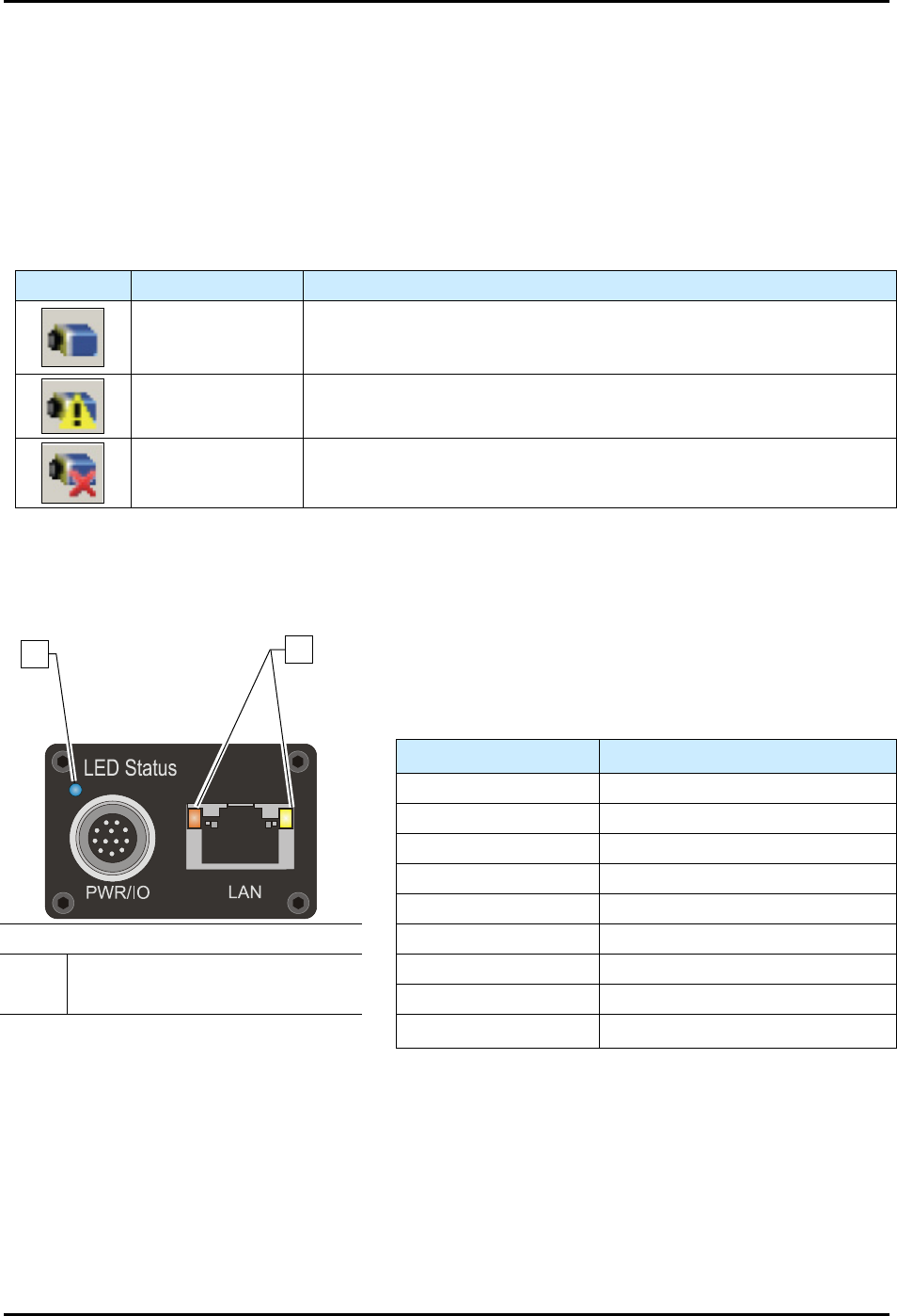
4.5 Camera States
The dispensing system features a Dalsa Genie M640 digital 640 x 480 pixel camera. The camera
communicates bi-directionally to the laptop computer via Gigabit Ethernet. After the Dalsa-Genie
software package has been installed, the GigE Server icon will be visible in the desktop taskbar tray area.
The icons and descriptions are shown in Table 4-1.
NOTE The Dalsa-Genie software is installed at the factory prior to shipping.
Table 4-1 Genie Camera States
Icon
State
Description
Device Available
The GigE server tray icon when the Genie device is found. It will
take a few seconds for the GigE Server to refresh its state after the
Genie has obtained an IP address.
Device IP Error
The GigE server tray icon shows a warning when a device is
connected but there is some type of IP error.
Device Not
Available
A red X will remain over the GigE server tray icon when the Genie
device is not found. This indicates a major network issue.
The Genie has one multicolor LED to provide a simple visible indication of camera state. Additionally,
the RJ45 has two LEDs for network status conditions (Figure 4-2). LED Status indicators are described in
Table 4-2.
Table 4-2 Camera Status Indicators
LED Status
Description
LED is OFF
No power to camera
Steady Red Camera Not Initialized
Slow Flashing Red Camera Initialization Problem
Fast Flashing Red
Camera Overheating
Steady Blue IP Address Assigned
Item
Description
Slow Flashing Blue Waiting for an IP Address
1 Camera Status LED Fast Flashing Blue Ethernet Cable Disconnected
2 Network Status LEDs Steady Green Application Linked to the Camera
Figure 4-2 Camera LEDs (Rear View)
Slow Flashing Green Trigger Acquisition in Progress
1
2
S2-9XXX Series Dispensing System IOM Manual Operation
4-4 © 2023 Nordson Corporation
4.6 Daily Routine Procedures
Table 4-3 contains a brief description and instructions for routine procedures that should be performed
daily before and after operating the dispensing system. See 6.4 Routine Maintenance Procedures for
routine maintenance procedures that should be performed daily.
Table 4-3 Daily Routine Procedures
Procedure
Description
STARTUP
Check Main Air Pressure
Ensure that the main air pressure is properly adjusted. If necessary,
adjust the main air pressure, see 3.14 Adjusting the Main Air Pressure.
Record the proper setting on the daily routine checklist for daily
reference.
Verify Exhaust Connection
(Optional)
Verify that the exhaust vent is properly connected to the facility exhaust
system ductwork.
Check Ventilation Airflow
(Optional)
Verify ventilation holes are clear from obstructions.
Inspect Hardware
Inspect the dispensing system for broken, loose, worn, or missing
hardware. Replace or repair as necessary.
Inspect Electrical and
Pneumatic Lines
Inspect the dispensing system for broken, loose, or frayed electrical and
pneumatic lines. Replace as necessary.
Inspect Conveyor
Inspect conveyor rollers, bearings, and chain for surface damage.
Ensure that no foreign material adheres to surfaces. Clean and replace
as necessary.
SHUTDOWN
Remove Workpieces
Remove all workpieces and foreign objects from the dispensing and
conveyor areas.
Clean Dispensing System
Clean all surfaces of the dispensing system (doors, side panels, front
panel, part sensor, etc.).
Clean/Replace Needle or
Mixertube
Refer to the applicable dispensing valve manual for instructions.