Spectrum+Operating+Manual.pdf - 第125页
S2-9 XXX Se ri es Dispensing Sys te m IOM Man ual Maintenance © 2023 Nordson C orporatio n 6-13 6.9.3 Rear Cable Cover To remove the rear ca ble covers ( Figure 6-8 ): 1. Perform a service shutd own, see 2.14 Service Shu…
S2-9XXX Series Dispensing System IOM Manual Maintenance
6-12 © 2023 Nordson Corporation
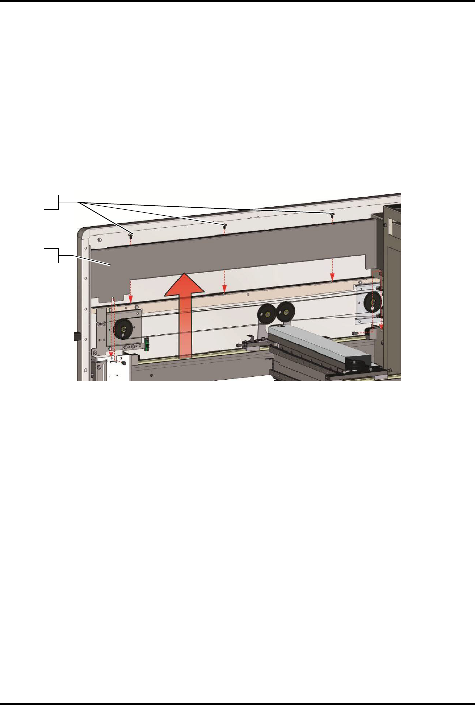
6.9.2 Y-Axis Cable Cover
This procedure is for both left or right Y-axis cable covers.
To remove the Y-axis covers (Figure 6-7):
1. Perform a service shutdown, see 2.14 Service Shutdown.
2. Open the dispensing area door.
3. Removing the top cover, see 8.7 Removing and Installing the Top Cover and Components.
4. Remove the three (3) screws securing the Y-axis cable cover to the Y-axis.
5. Remove the Y-axis cable cover.
Item
Description
1 Y-Axis Cable Cover
2 Screws (3)
Figure 6-7 Removing the Y-Axis Covers
To install the Y-axis cable cover (Figure 6-7):
1. Install the three (3) screws securing the Y-axis cable cover to the Y-axis.
2. Torque the three (3) screws to 5.6 Nm (50 in-lbs).
3. Install the top cover, see 8.7 Removing and Installing the Top Cover and Components.
4. Close the dispensing area door.
2
1
S2-9XXX Series Dispensing System IOM Manual Maintenance
© 2023 Nordson Corporation 6-13
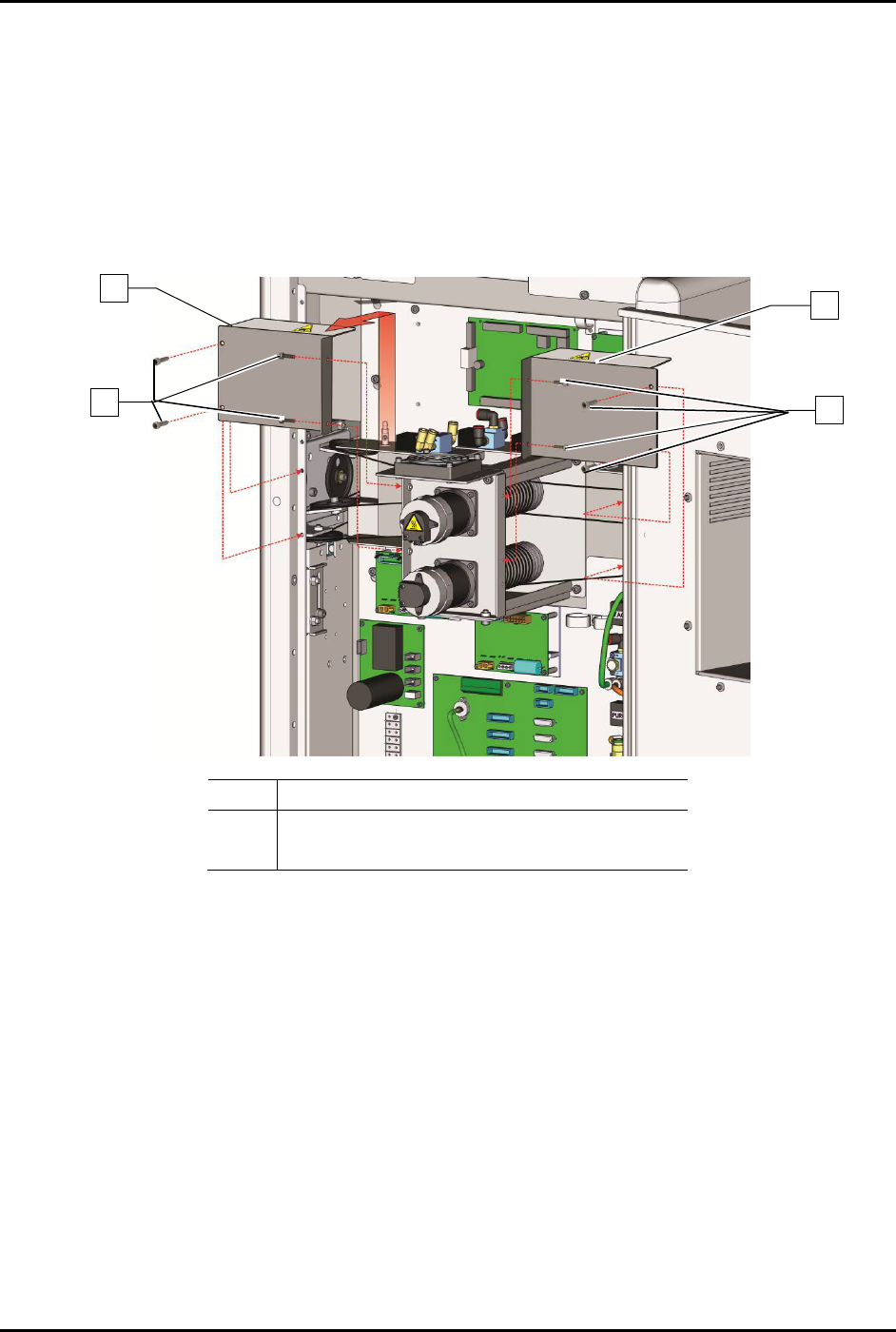
6.9.3 Rear Cable Cover
To remove the rear cable covers (Figure 6-8):
1. Perform a service shutdown, see 2.14 Service Shutdown.
2. Open the rear dispensing area door.
3. Remove the eight (8) screws securing the rear cable covers to the dispensing system.
4. Remove the rear cable covers.
Item
Description
1 Screws (8)
2
Rear Cable Covers
Figure 6-8 Removing the Rear Cable Covers
To install the rear cable covers (Figure 6-8):
1. Install the eight (8) screws securing the rear cable covers to the dispensing system.
2. Torque the eight (8) screws to 2.8 Nm (25 in-lbs).
3. Close the rear dispensing area door.
2
1
2
1
S2-9XXX Series Dispensing System IOM Manual Maintenance
6-14 © 2023 Nordson Corporation
6.10 Lubricating the Cables and Linear Guides
The XYZ-axes support the dispensing head and allow it to travel within the dispensing area. To ensure
smooth dispensing head movement, the cables and linear guides must be lubricated approximately every
three months.
NOTE To perform the following procedures, you will need Asymtek Grease Kit (Item 58). The
kit contains a grease pump, two cartridges of grease, and a lint-free cloth.
Tools and Materials Needed
• Safety Glasses
• Rubber Gloves
WARNING! Refer to the applicable Safety Data Sheet for materials used in this procedure for
important safety information.
6.10.1 Loading the Grease Gun
To load the grease gun:
1. Unscrew and remove the grease pump from the grease gun canister.
2. Remove the cap from the grease cartridge.
3. Remove the seal and screw the grease cartridge into the grease pump.
4. Fit the canister of the grease gun over the grease cartridge and screw into the grease pump.
5. Screw the nozzle into the grease pump.
6. Screw the grease fitting adapte
r into the nozzle.
7. Purge the air from the grease gun cartridge by dispensing grease into a waste receptacle
until a solid stream flows from the grease gun.
6.10.1 Lubricating the Cables
NOTE Use Moly-Graph grease included in the Grease Kit (Item 58). DO NOT USE FOR
CLEANROOM SYSTEMS! See warning below.
WARNING! For S2-9X0 Series Cleanroom Systems, use only NSK Clean Grease LG2
(Item 58) included in your grease kit.
To lubricate the cables:
1. Perform a service shutdown, see 2.14 Service Shutdown.
2. Open the dispensing area door.
3. Remove the axis and cable covers, see 6.9 Removing and Installing the Axis Covers.