Spectrum+Operating+Manual.pdf - 第94页
S2-9 XX X Se ri es Disp ensi n g Syst em IOM Man ual Calibration and Adjus tment 5-18 © 2023 Nordson Corporatio n 5.10.3 Adjustin g th e Co ol ing/Coaxial, Val ve, and F l uid Air Pressure To adjust the cooling/co axial,…
S2-9XXX Series Dispensing System IOM Manual Calibration and Adjustment
© 2023 Nordson Corporation 5-17
5.10.2 Adjusting the Tooling Air Pressure
The tooling air pressure regulates air supplied to the stop pins and lift tables. The regulator receives air
from the main air regulator located on the back of the dispensing system.
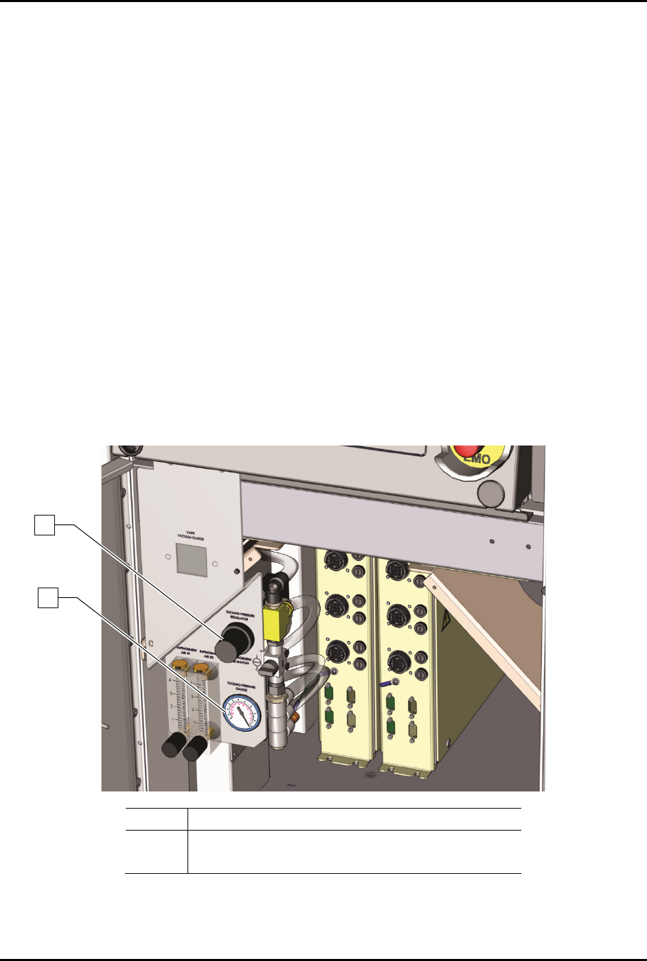
To adjust the tooling air pressure (Figure 5-19):
1. Locate the tooling air pressure regulator adjustment knob in the front cabinet.
2. Rotate the adjustment knob counterclockwise until the gauge registers 0 psi.
3. Rotate the adjustment knob clockwise until the associated gauge registers the air pressure
value (kPa or psi) required by your dispensing application.
For accurate pressure adjustment, lower the pressure below the desired level and then
increase to the desired pressure.
NOTE Pressure settings depend on the fluid being dispensed and dispensing valve
being used. Refer to the applicable dispensing valve manual for additional
information.
4. Monitor the tooling pressure gauge to make sure that pressure builds at a steady rate. A drop
in air pressure can indicate an air leak.
If there is an air leak, identify the source, shut off the facility air, and fix the leak before
proceeding.
Item
Description
1 Tooling Pressure Regulator
2
Tooling Pressure Gauge
Figure 5-19 Adjusting the Tooling Pressure Regulator
1
2
S2-9XXX Series Dispensing System IOM Manual Calibration and Adjustment
5-18 © 2023 Nordson Corporation
5.10.3 Adjusting the Cooling/Coaxial, Valve, and Fluid Air Pressure
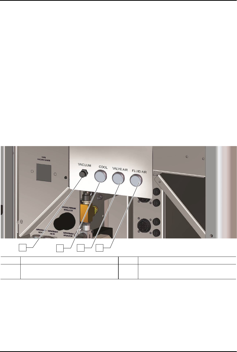
To adjust the cooling/coaxial, valve, and fluid air pressure (Figure 5-20):
1. Locate the desired air pressure regulator adjustment knobs in the front cabinet.
2. Rotate the adjustment knob counterclockwise until the gauge registers 0 psi.
3. Rotate the adjustment knob clockwise until the associated gauge registers the air pressure
value (kPa or psi) required by your dispensing application.
For accurate pressure adjustment, lower the pressure below the desired level and then
increase to the desired pressure.
NOTE Pressure settings depend on the fluid being dispensed and dispensing valve
being used. Refer to the applicable dispensing valve manual for additional
information.
4. Monitor the pressure gauge to make sure that pressure builds at a steady rate. A drop in air
pressure can indicate an air leak.
If there is an air leak, identify the source, shut off the facility air, and fix the leak before
proceeding.
Item
Description
Item
Description
1
Vacuum Control Regulator
3
Valve Air Regulator
2
Cooling/Coaxial Air Regulator
4
Fluid Air Regulator
Figure 5-20 Adjusting the Valve and Fluid Pressure Regulators (S2-9XX/A shown)
NOTE Programmable fluid and valve pressure is an option. Refer to the Fluidmove User Guide
or Fluidmove Online Help for instructions on using the E/P option.
1
2
3
4

S2-9XXX Series Dispensing System IOM Manual Calibration and Adjustment
© 2023 Nordson Corporation 5-19
5.10.4 Adjusting the Vacuum Control
The vacuum control (Figure 5-24) allows low viscosity fluids to be consistently dispensed without
dripping between cycles. The vacuum exerts a negative pressure (suckback) on the fluid, thereby
decreasing dripping.
To adjust the vacuum control:
1. Rotate the knob counterclockwise to increase vacuum pressure and decrease dripping.
2. Rotate the knob clockwise to decrease vacuum pressure.
5.10.5 Setting the Low-Pressure Detection Threshold
This feature allows the user to set the air pressure level at which the software will issue an on-screen low
air pressure error message. Refer to the Fluidmove User Guide or Fluidmove Online Help for
instructions.