Spectrum+Operating+Manual.pdf - 第52页
在线预览 Spectrum+Operating+Manual.pdf PDF 文档。
S2-9XXX Series Dispensing System IOM Manual Safety
© 2023 Nordson Corporation 2-19
2.16 Light Beacon
The light beacon is a device that displays system status and can warn the operator when fault conditions
exist. The beacon has red, yellow, green, and blue lights that can be solid or flashing. The beacon also has
an audible alarm. Table 2-4 provides possible reasons for each color indication.
Software and hardware share control of the beacon lights. Sometimes, hardware-driven displays override
those caused by software conditions and sometimes software-driven displays override. Safety critical
conditions always have priority. Flashing light software commands have priority over solid light
commands.
NOTE Light beacon action can be custom configured using the beacon control feature. Refer to
the Fluidmove User Guide or Fluidmove Online Help for details.
See Section 7 - Troubleshooting for suggested recovery from common fault conditions.
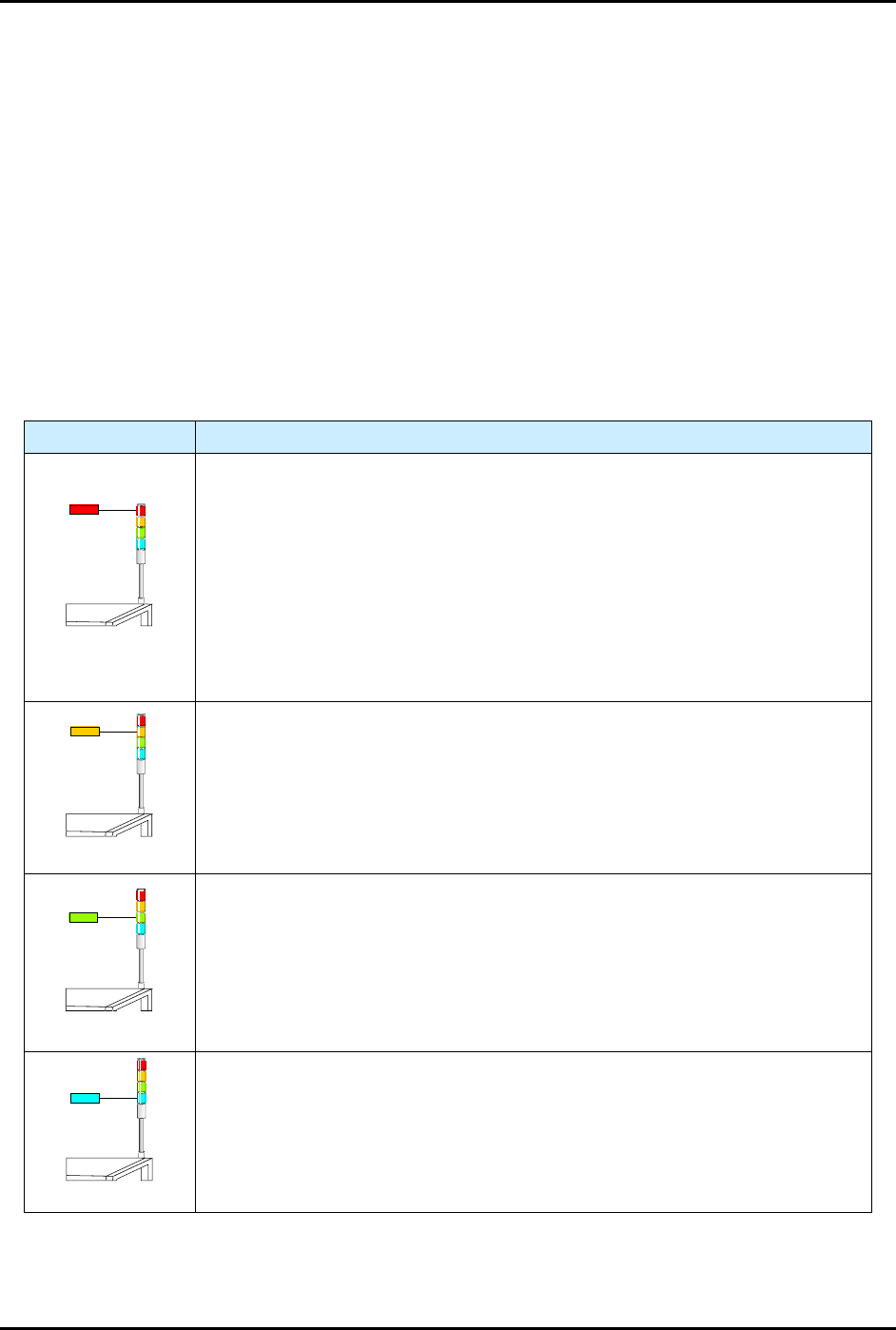
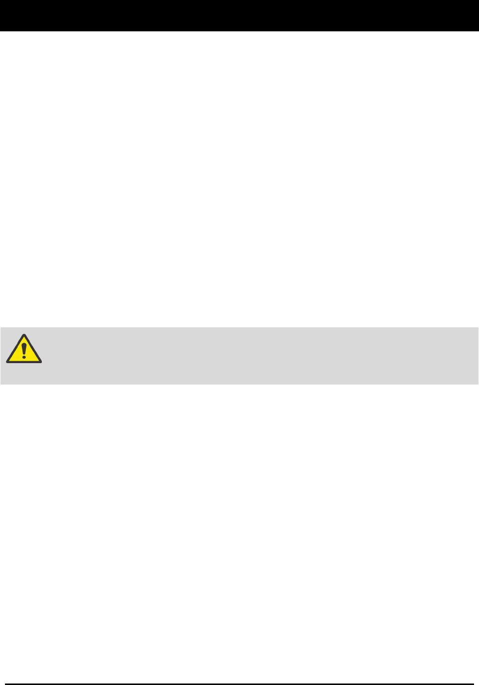
Table 2-3 Light Beacon Color Indications
Beacon Color System Status
RED
ALERT
All motion, outputs, dispensing valve, and motion controls are disabled until
the fault is cleared.
One of the following conditions may exist:
A. Solid - Emergency stop condition or heater error.
B. Flashing - General error or vision error. Software driven error message is
displayed on the computer monitor.
C. Solid or Flashing - Software has been configured to display a solid or
flashing red light.
YELLOW
CAUTION
System in a low power state or lacks sufficient air pressure.
One of the following conditions may exist:
A. Solid - Front door is open (Interlock activated).
B. Solid or Flashing - Software has been configured to display a solid or
flashing yellow light.
GREEN
OPERATION
One of the following conditions may exist:
A. Solid - The system is fully operational with the front door closed.
B. Solid or Flashing - Software has been configured to display a solid or
flashing green light.
BLUE
USER DEFINED
A. Solid - Software has been configured to display a solid blue light.
B. Flashing - Software has been configured to display a flashing blue light.
© 2023 Nordson Corporation 3-1
3 Installation
3.1 Overview
This section describes installation procedures for the dispensing system and covers the following topics:
• Uncrating and Placing the Dispensing System
• Installing the Laptop Computer
• Unpacking the Dispensing Chamber
• Anchoring the Dispensing System
• Leveling the Dispensing System
• Installing the Dovetail Bracket
• Setting Up the Service Station
• Connecting the Power and Air Supply
• Installing the Light Beacon
• Adjusting the Main Air Pressure
3.2 Safety First
Operation of your dispensing system involves heat, air pressure, electrical power, mechanical devices,
and the use of hazardous materials. Read this manual in its entirety before attempting any system or
component operation. It is essential for all personnel working on or around the dispensing system to fully
understand the hazards, risks, and safety precautions associated with operating the system. When properly
operated and maintained, the dispensing system is safe and reliable. See Section 2 - Safety for additional
information.
WARNING! The procedures in this section should only be performed by a trained
service technician.
3.3 Facility Requirements
To ensure optimal performance and safety, it is necessary to install the dispensing system in a facility that
meets the requirements, see 9.2 Facility Requirements. If you have any questions about facility
requirements, please contact Asymtek Technical Support.
3.4 Tools and Materials Needed
• 3 mm hex key
• 1/2-inch wrench
• 9/16-inch wrench
• Phillips Screwdriver (Item 59)
• Band Cutter
• 1 1/2-inch wrench (Item 59)
• Personal Protective Equipment
• Diagonal-cut pliers
• Hammer
• Forklift
• Flat Bar
• Box Level