Spectrum+Operating+Manual.pdf - 第90页
S2-9 XX X Se ri es Disp ensi n g Syst em IOM Man ual Calibration and Adjus tment 5-14 © 2023 Nordson Corporatio n 5.9 Calibrating the E/P Con trolle rs If the dispensing syst em is configur ed with the o ptio nal e l ect…
S2-9XXX Series Dispensing System IOM Manual Calibration and Adjustment
© 2023 Nordson Corporation 5-13
7. If the threshold value is not in the range of the present/not present values, follow the steps
below to adjust the light level. Step 7a through Step 7e are only required if the board sensor
does not respond correctly after adjustment.
a. Press and hold the
Mode button for 3 seconds until [Func dFLt] (or [Func oPt])
begins to blink on the display.
b. Click
Mode button once. You will see [HS] followed by a number.
c. Click the (
+) button until you see [Stnd]. Press and hold Mode until the two sets of
numbers appears again.
d. If the threshold number is still not within the range of values, repeat Step 7b and
Step 7c, but this time click the (
+) button until you see [GIGA].
e. If threshold is still not within range, the fiber optic sensor will need to be moved closer
to the carrier/board.
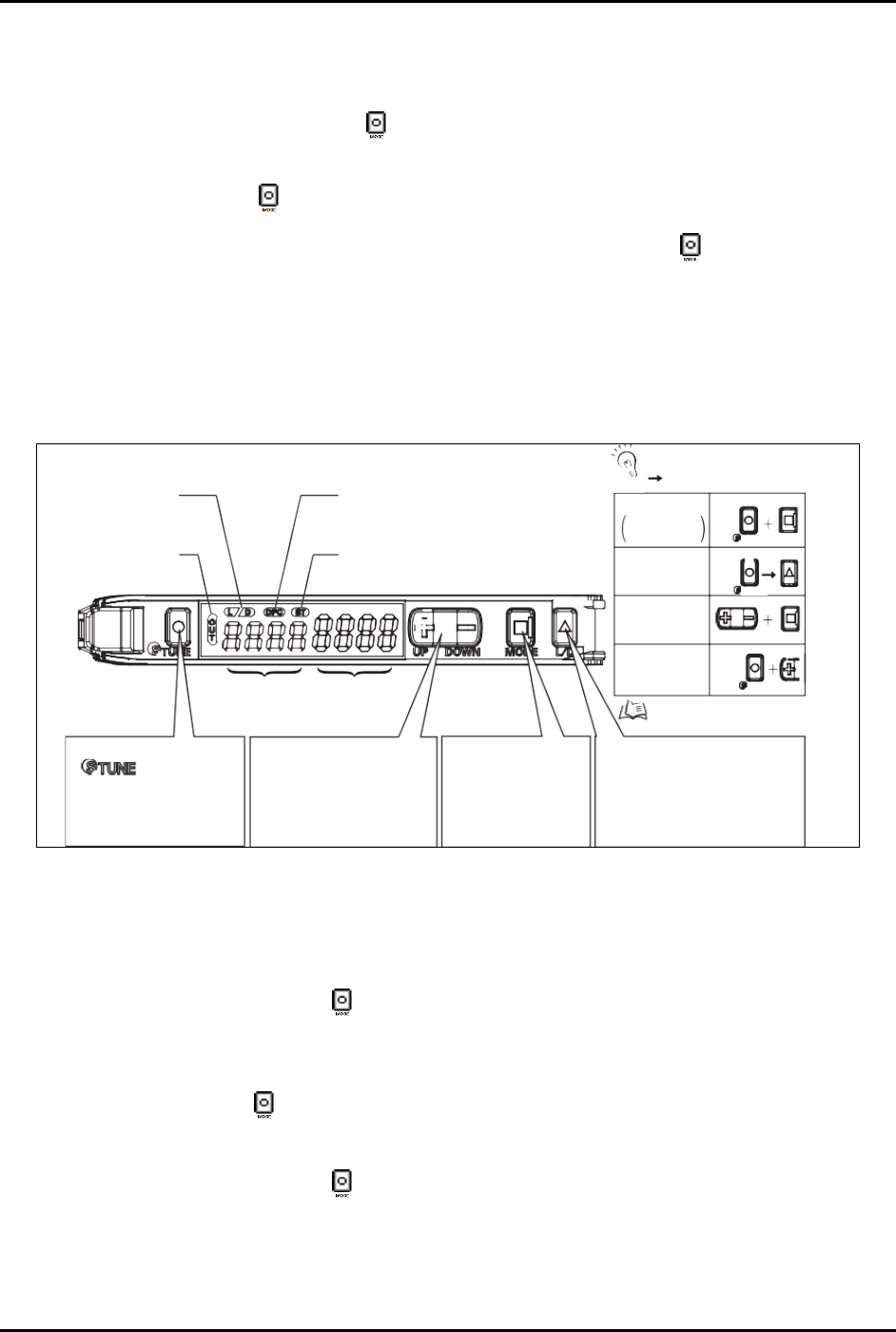
Power Tuning
When Light
Level is
Saturated
Setting Reset
Key Lock
Zero Reset
MODE
MODE
L/D
UP/DOWN
[DPC Indicator]
Turns ON when Dynamic Power Control is
effective.
[ST Indicator]
Turns ON when Smart Tuning is in progress.
Refer to “Convenient
Setting Features”.
TUNE
TUNE
TUNE
Output Switch
[LD] Button
A single press switches between
Light ON/Dark ON. [L/D] indicator
changes.
Mode Change
[MODE] Button
Switches between SET
mode and RUN mode by
a long press (3 seconds
or longer) of the key.
Sensitivity Setting
[
] Button
A single press for each setting
with/without a workpiece.
[ST Indicator] turns ON.
Minute Threshold
Adjustment
[UP/DOWN] Button
The green digital value changes.
Threshold Level
Green Digital Display
Incident Light
Level
Red Digital Display
[LD Indicator]
Displays
Light ON/Dark O setting.
[OUT Indicator]
Turns ON when Output is
ON.
+
: Press both
: Press both in sequence
UP
CHECK!
Figure 5-14 Board Sensor Setting and Display Overview
5.8.2 Inverting the Display
To invert the display (Figure 5-14):
1. Press and hold the
Mode button for 3 seconds until [Func dFLt] begins to blink on the
display.
2. Click the
Up (+) button once so that [Func oPt] appears.
3. Press the
Mode button until [rEv oFF] is shown.
4. Click the
Up (+) button once so that [rEv on] appears.
5. Press and hold the
Mode button for 3 seconds until the two sets of numbers appear.
After inverting the display, the above diagram will be reversed; the green numbers will
represent the current light level and the red numbers will represent the threshold.
S2-9XXX Series Dispensing System IOM Manual Calibration and Adjustment
5-14 © 2023 Nordson Corporation
5.9 Calibrating the E/P Controllers
If the dispensing system is configured with the optional electronic pressure control utility, follow the
procedure below to calibrate the E/P controllers. During the calibration process, you will ensure that the
Fluidmove pressure set point and Fluidmove pressure reading matches the external pressure gauge
reading.
NOTE This procedure assumes that the dispensing system is ON and Fluidmove is running.
Tools and Materials Needed:
• External Pressure Gauge
• Quick Disconnect Fitting
To calibrate the Fluidmove set point with the external gauge reading:
1. In the Fluidmove Main Window, select
Configuration > Setup Runtime Preferences >
Local Machine Offsets
.
The Local Machine Offsets window opens.
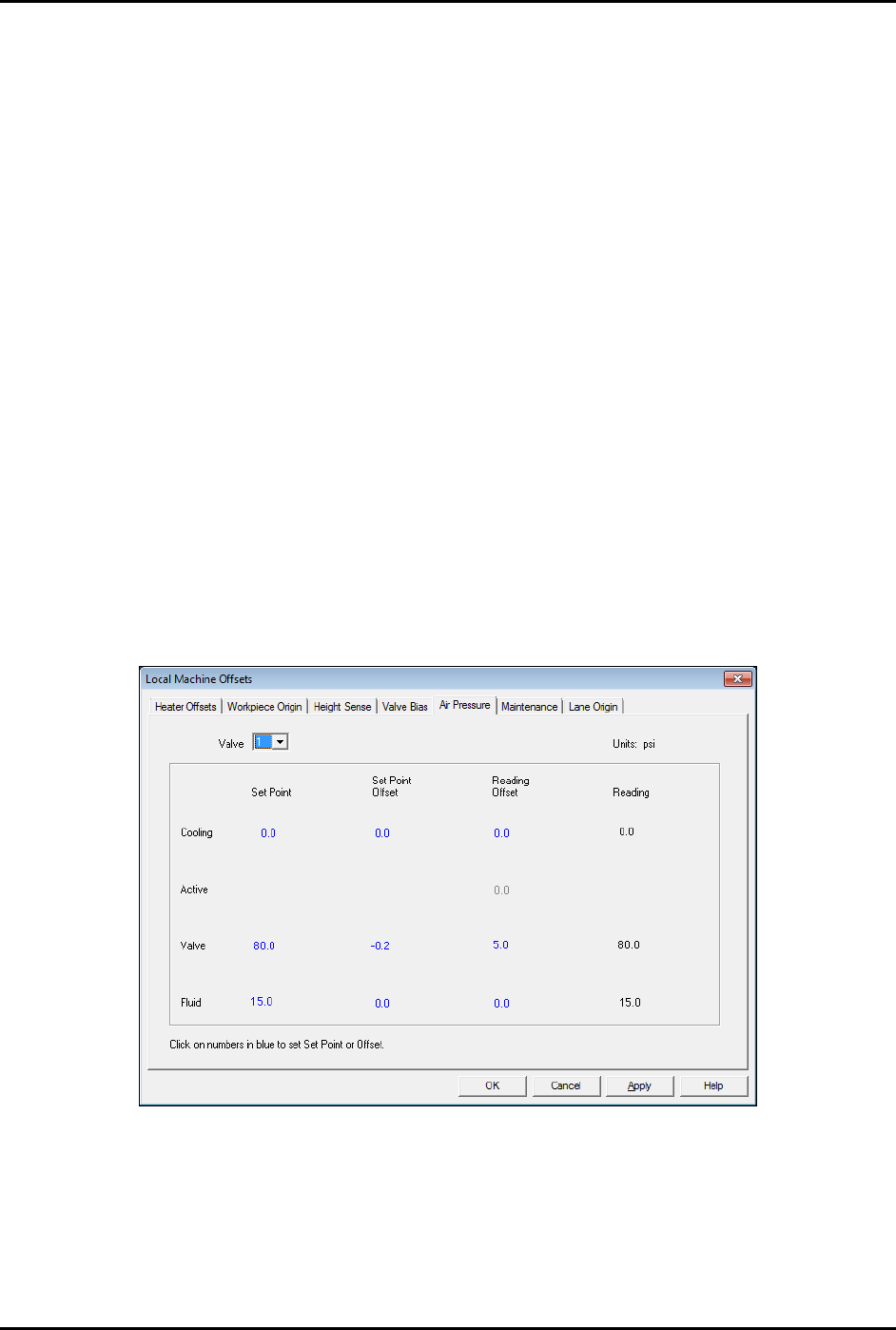
2. Select the Air Pressure tab (Figure 5-15).
This tab displays the Set Point, Set Point Offset, Reading Offset and Reading for
cooling, valve, and fluid pressure. The value in the “Reading” column is the same as the
value in the Current Pressure window (Figure 5-17) accessed by pressing [Ctrl + P] on
the dispensing system keyboard.
Figure 5-15 Local Machine Offsets - Air Pressure Tab
3. To establish air pressure set points, click on the numbers in blue, enter the desired values
and press enter. Click on
OK.
It is best to calibrate valve air pressure with the same pressure setting that will be used
in the dispensing program. It is not necessary for cooling and fluid pressure adjustment.
S2-9XXX Series Dispensing System IOM Manual Calibration and Adjustment
© 2023 Nordson Corporation 5-15
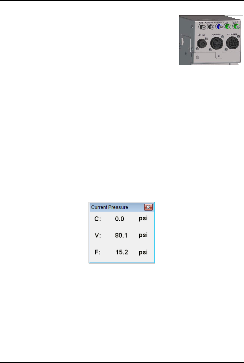
4. Connect the external pressure gauge to the desired connection
(valve, fluid, or cooling) on the dispensing system bulkhead
(Figure 5-16) using a quick disconnect fitting.
For the valve pressure reading, insert the external pressure
gauge hose into the black Valve 1 Off connection on the
bulkhead. If there is no reading, connect the hose to the
blue Valve 1 ON connection.
You should now have a reading at the digital gauge.
5. Compare the external gauge pressure reading to the set point
displayed on the Air Pressure tab (Figure 5-15).
Figure 5-16 Dispensing
System Bulkhead
6. If the pressure reading on the external pressure gauge does not match the software set
point, click on the value in the "Set Point Offset" column and enter the difference between
the actual output (reading on the external gauge) and the set point on the Air Pressure tab.
Click on
Apply. A positive value will increase the output, and negative value will lower
the output. For example, if the gauge reading is 80.2 and the software set point is 80.0,
enter -0.2 in the “Set Point Offset” column. The external gauge output should now be 80.0.
After the set point has been calibrated, it is necessary to calibrate the external pressure
gauge to the software reading.
To calibrate the Fluidmove current pressure reading to the external gauge reading:
1. Press [Ctrl + P] on the dispensing system keyboard to open the Current Pressure window
(Figure 5-17).
The current pressure is the same as the pressure shown in the “Reading” column on the
Air Pressure tab in the Local Machine Offsets window (Figure 5-15).
Figure 5-17 Current Pressure Window
2. If the reading on the external gauge does not match the current pressure reading in the
software, click on the value in the “Reading Offset” column (Figure 5-15) and enter the
difference between the actual output (reading on the digital gauge) and the reading on the
Air Pressure tab. Click on
Apply.
A positive value will increase the reading, and negative value will lower the reading.
For example, if the gauge reading is 80.0 and the software reading is 75.0, enter 5.0 in
the Reading Offset column. The software reading will change to 80.0.
3. When all applicable outputs have been calibrated, click
OK in the Local Machine Offsets
Window. The values are now set and the E/P controllers are calibrated.