Spectrum+Operating+Manual.pdf - 第143页
S2-9 XXX Se ri es Dispensing Sys te m IOM Man ual Troubleshootin g © 2023 Nordson C orpor ation 7-5 7.4.4 Fluidmove Star tup Table 7-4 F luidmove St artup Symptom Po ss ible Cause Recovery “The Dispense r ACLPlus Device …

S2-9XXX Series Dispensing System IOM Manual Troubleshooting
7-4 © 2023 Nordson Corporation
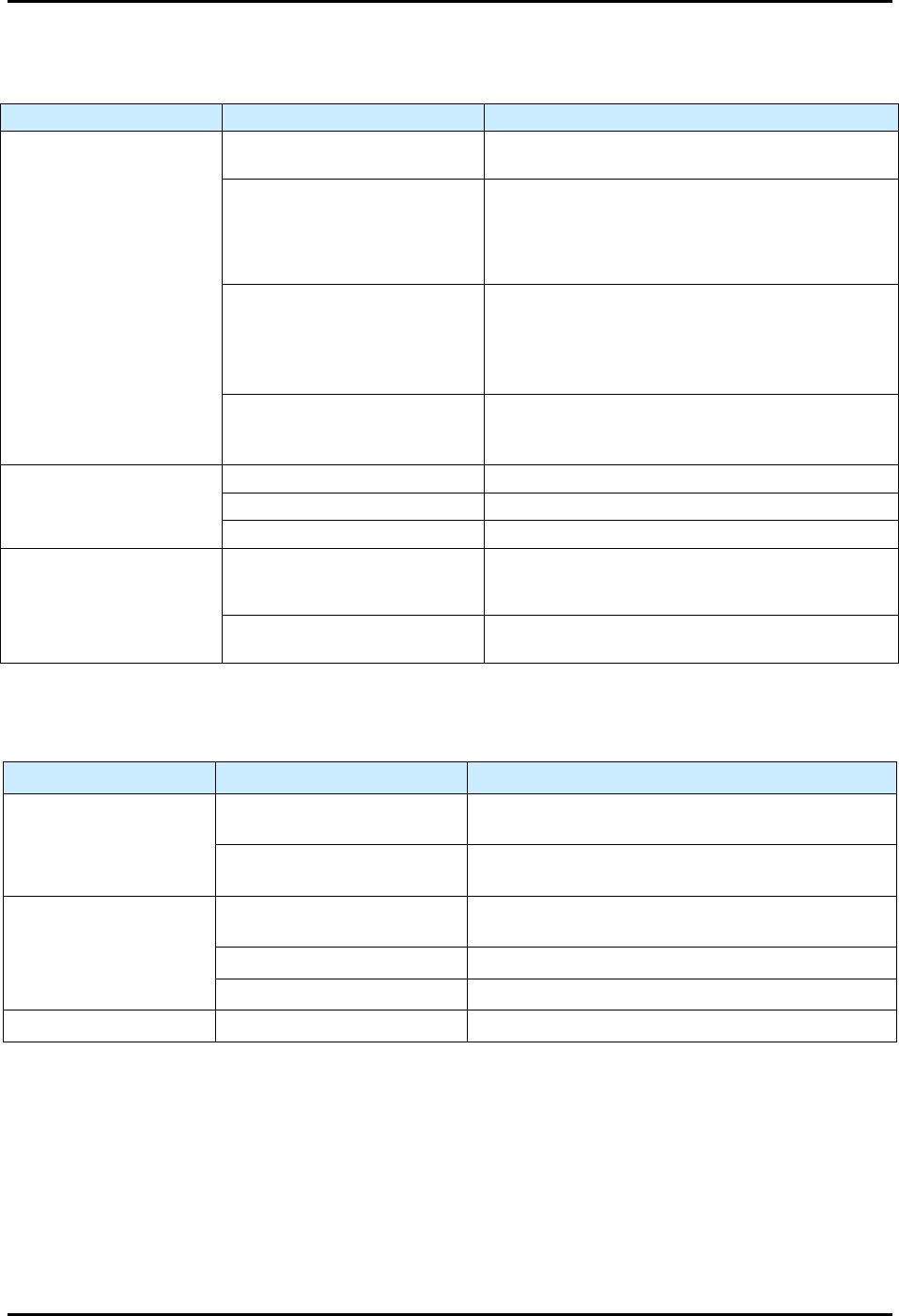
7.4.3 Dispense Head Controller Connections and Functions
Table 7-3 Dispensing Head Troubleshooting
Symptom Possible Cause Recovery
Dispense Head
Controller fails to initialize
during Fluidmove startup
CAN terminator not present. Verify presence of CAN terminator.
Corrupt firmware or incorrect revision.
CAN firmware may need to be flashed to the
correct or latest firmware. Contact Asymtek
Technical Support.
Failed dispense head controller.
Verify DHC power indicator LEDs for
3.3V, -12V, and 12V are illuminated.
A fuse on the PDHC may have blown.
If power indicator lights on PDHC are not
illuminated, replace fuse, see 8.16 Replacing
Fuses.
Dispenses at wrong
Z-Axis position
Height sensor has been adjusted or is
loose.
Adjust height sensor and tighten locking screw,
see 5.12 Adjusting the Height Sensor Probe
(Option).
Nozzle/needle has been changed.
Perform a “Valve Offsets” or “Calculate Master
Offsets” routine in Fluidmove. For assistance,
refer to the Fluidmove User Guide or Fluidmove
Online Help.
No fluid dispensing
Valve setup incorrect.
Verify the valve type set in Fluidmove matches
the dispensing valve, and that the valve is
plugged into the pump connector on the
dispense head.
Valve Fatal Following Error (FFE).
1. Ensure valve does not have cured material
inside of it.
2. Exit Fluidmove, cycle power to the machine,
and retry.
3. PID parameters are not correct. Contact
Asymtek Technical support for correct PID
parameters for the particular pump being
used (applicable to the DV-7000, DV-8000,
and DP-2000 only).
Z-Axis Noise
Z counterbalance springs are not set
up correctly.
With the dispensing area door open, manually
lower the valve about 25 mm (1 in). When you
let go of the valve, it should neither rise nor fall.
If it does, you will need to adjust the Z-head
counterbalance, see 5.7 Adjusting the Z-Head
Counterbalance Force.
Wrong tuning file is loaded into the
machine.
The tuning values are set at the factory
according to the system configuration (single
valve vs. dual valve set up). To change tuning
files, contact Asymtek Technical Support.
S2-9XXX Series Dispensing System IOM Manual Troubleshooting
© 2023 Nordson Corporation 7-5
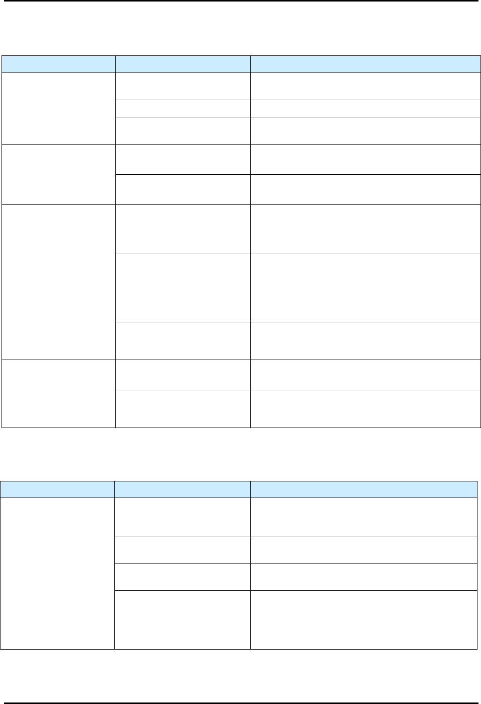
7.4.4 Fluidmove Startup
Table 7-4 Fluidmove Startup
Symptom
Possible Cause
Recovery
“The Dispenser ACLPlus
Device Failed to Respond”
message appears
Communications failure.
Verify COM port settings and serial communications
cables are attached. Restart computer and retry.
USB communications failure.
The USB hub may have failed or lost power. The
laptop PC communicates to system devices via the
USB hub. Check the USB connection and ensure
the USB hub is connected to its power source on
outlet AC4 from the power manager.
Main PWA NVRAM failure.
1. Replace battery and reinitialize Main PWA
memory.
2. Run escape sequences and reload machine
specific personalities. Refer to the system’s ACL
recovery disk.
Main PWA failure.
1. Check main PWA’s “Heartbeat” to see if board is
functioning. Cycle power and retry.
2. Replace fuse, see 8.16 Replacing Fuses.
No dispensing head
motion
No system power. See Table 7-1.
Interlock open. Restore Interlock, see 2.13.1 Interlock Recovery.
Home cable disconnected. Connect cable.
Dispensing head fails to
find home
Obstruction preventing machine
motion, and the servo system
goes open loop.
Remove obstruction.
Home switch failure.
Inspect and adjust home flag and retry. Replace
home switch if broken.
7.4.5 Laser Height Sensor
Table 7-5 Laser Height Sensor Troubleshooting
Symptom Possible Cause Recovery
Height Sensor does not
power up
Height sensor is not plugged in.
Check power connection and verify that height sensor
plugged in.
Bad resistor on the main board
d-sub connection.
Use a multimeter to verify that the main board d-sub
resistor is good.
Height Sensor does not
trigger
Dip switches not set properly.
Verify that dip switch number 6 on SW1 on the main
board is set to on.
Height sensor lens is dirty. Check and clean the height sensor lens.
No communication with PC. Verify I/O tools can toggle height sensor bits.
Intermittent function Loose or frayed cables. Check cables for tight connection and wear.
S2-9XXX Series Dispensing System IOM Manual Troubleshooting
7-6 © 2023 Nordson Corporation
7.4.6 Mechanical/Tactile Height Sensor
Table 7-6 Height Sensor Troubleshooting
Symptom Possible Cause Recovery
Probe does not drop or
retract
Probe is damaged.
Check for bent probe. Replace if necessary, see 8.10.2
Replacing the Mechanical/Tactile Height Sensor Probe.
No air pressure. Verify main air pressure is ON (I).
Pneumatic hose is kinked or
pinched.
Check pneumatic lines.
Probe either drops too
slowly or slams down with
too much force
Main air pressure not set
properly.
Readjust main air pressure regulator to system’s
nominal pressure.
Pneumatic hose is kinked or
pinched.
Check pneumatic lines.
Needle hits substrate
Probe tip is lower than the
needle tip when valve is in
dispensing position.
Adjust probe and perform “Valve Offsets” in Fluidmove,
see 5.12 Adjusting the Height Sensor Probe (Option).
Refer to the Fluidmove User Guide or Fluidmove
Online Help.
The height sensor is not set up
properly.
Test the height sensor. Fluidmove provides a height
sensor test utility from the Tools > Diagnostics
menu.
The probe can be toggled up and down to verify probe
functionality. There is also a test procedure that
captures HS trigger values. Fluidmove can display a
statistical analysis of the captured values.
HS velocity is set too high.
Reduce the HS velocity to 2 inches per second and re-
run the valve offsets. Test the height sensor from the
diagnostics menu if necessary.
Probe hits substrate
before it is fully extended
Safe Z height too low.
Reteach safe Z height. Refer to the Fluidmove User
Guide or Fluidmove Online Help.
Retract distance too low.
Reteach the retract distance in the height sensor setup.
Refer to the Fluidmove User Guide or Fluidmove
Online Help.
7.4.7 Needle Heater
Table 7-7 Needle Heater Troubleshooting
Symptom Possible Cause Recovery
No needle heat
Set Point (SP) value below
Present Value (PV) or the
heater is in an idle state.
Change the SP value within the Heater Controls
window. Refer to the Fluidmove User Guide or
Fluidmove Online Help.
Disconnected heater.
Verify the needle heater cable connections are
securely attached to the correct ports.
Failed DHC power.
Verify DHC indicator lights for 3.3V, -12V, and 12V
are illuminated.
Failed heater.
Verify the needle heater electrical parameters. The
resistance between pins 4 and 5 for the heating
element should be 100 ohms +/- 5 ohms. The
resistance of the RTD sensor between pins 6 and 7
should be 108 ohms, +/- 5 ohms.