Spectrum+Operating+Manual.pdf - 第189页
S2-9 XXX Se ri es Dispensing Sys te m IOM Man ual Parts Replacement © 2023 Nordson C orpor ation 8-37 8.16.4 Replacing the Impingement Flowmeters To remove the impingement fl owmeters (Figu re 8- 28 ): 1. Remove the pneu…
S2-9XXX Series Dispensing System IOM Manual Parts Replacement
8-36 © 2023 Nordson Corporation
To install the pressure gauge:
1. Install the pressure gauge with fitting through the pneumatics panel assembly.
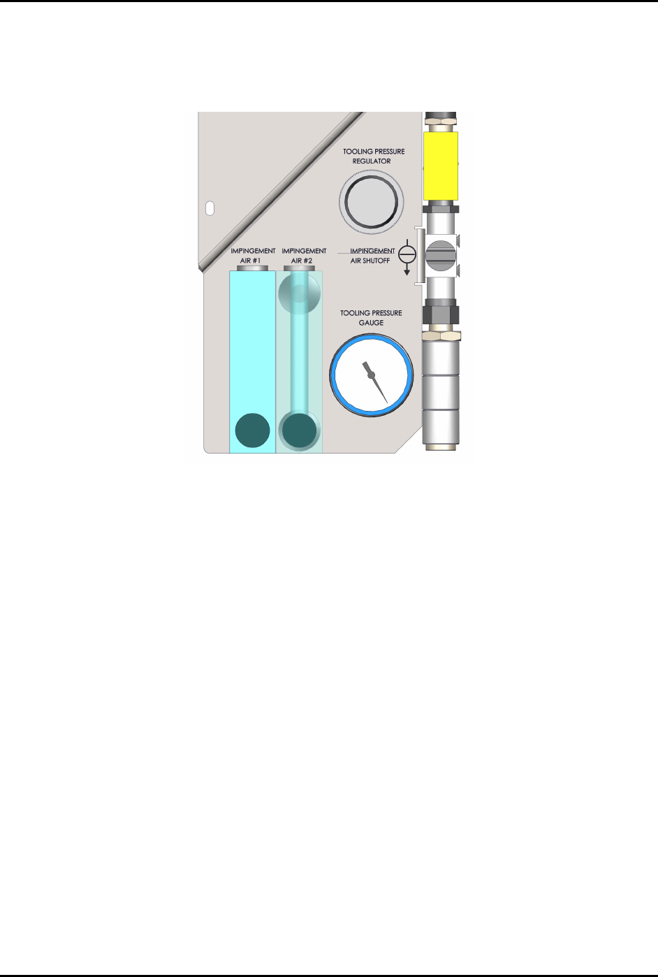
Orient the pressure gauge as shown in Figure 8-27.
Figure 8-27 Pressure Gauge Orientation
2. From the rear of the pneumatics panel assembly, install the mounting ring over the pressure
gauge and install two (2) screws securing the pressure gauge to the pneumatics panel
assembly (Figure 8-26).
3. Connect the pneumatic connection to the pressure gauge.
4. Reattach the pneumatics panel to the dispensing system, see 8.14.1 Removing and Installing
the Pneumatics Panel.
S2-9XXX Series Dispensing System IOM Manual Parts Replacement
© 2023 Nordson Corporation 8-37
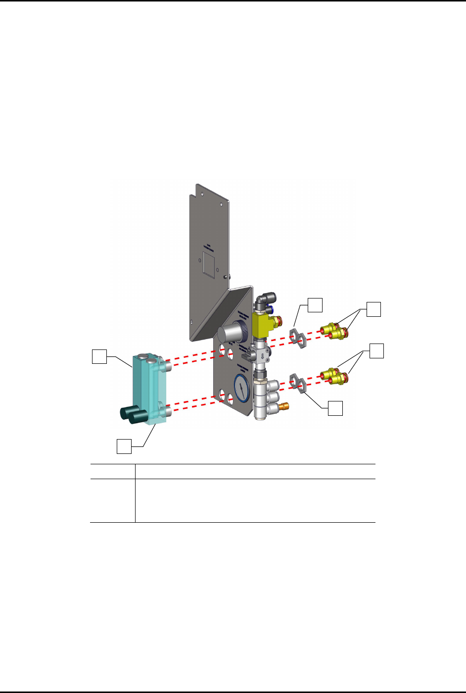
8.16.4 Replacing the Impingement Flowmeters
To remove the impingement flowmeters (Figure 8-28):
1. Remove the pneumatics panel, see 8.14.1 Removing and Installing the Pneumatics Panel.
2. Disconnect the pneumatic connection from the regulator.
Note the connection location.
3. From the rear of the pneumatics panel assembly, remove the four (4) fittings and four (4)
nuts.
4. Remove the two (2) flowmeters.
Item
Description
1
Flowmeter
2
Nuts (2 each gauge)
3
Fittings (2 each gauge)
Figure 8-28 Replacing the Impingement Flowmeters
To install the flowmeters (Figure 8-28):
1. Insert the flowmeters into the pneumatics panel assembly and install the four (4) nuts and
four (4) fittings.
2. Torque to 9.8 Nm (87 in-lbs).
3. Reconnect the pneumatic connections.
4. Reattach the pneumatics panel to the dispensing system, see 8.14.1 Removing and Installing
the Pneumatics Panel.
2
1
1
2
3
3
S2-9XXX Series Dispensing System IOM Manual Parts Replacement
8-38 © 2023 Nordson Corporation
8.17 Replacing Components Inside the Rear Door Panel
Tools and Materials Needed:
• Hex Wrench (Item 59)
• Torque Wrench
• Switch Mounting Tool
• Thread Lock-Plastic Adhesive
WARNING! Ensure the dispensing system has been completely shutdown before attempting to
remove or install any panel, electrical component, or pneumatic component.
8.17.1 Replacing the Rear EMO Actuator Switch
To remove the rear EMO actuator switch (Figure 8-29):
1. Perform a service shutdown, see 2.14 Service Shutdown.
2. Open the rear door of the dispensing system.
3. Loosen two (2) screws securing the EMO rear bracket to the dispensing system and remove
the EMO rear bracket from the dispensing system.
WARNING! The EMO actuator switch must be supported during removal as there are cable
connections from the dispensing system to the EMO actuator switch. Not
supporting the EMO actuator switch may cause wiring and cable connector
damage.
4. Disconnect the power control cables from the EMO contact block switch.
5. Unplug the EMO contact block from the EMO actuator switch.
6. From the rear of the E-stop rear bracket using the switch mounting tool, remove the nut
securing the EMO actuator switch.
7. Remove the EMO actuator switch and EMO switch guard from the EMO rear bracket.