Spectrum+Operating+Manual.pdf - 第55页
S2-9 XXX Se ri es Dispensing Sys te m IOM Man ual Installation © 2023 Nordson Co rporat ion 3-3 6. When the four shippi ng brackets have been removed, slide the forklift forks under the front of the dispens ing sy ste m …
S2-9XXX Series Dispensing System IOM Manual Installation
3-2 © 2023 Nordson Corporation
3.5 Uncrating and Placing the Dispensing System
To uncrate and place the dispensing system:
1. Check the “Tip & Tell” and "Shockwatch" devices, both on the outside of the shipping crate
and on the dispensing system, to make sure that the dispensing system has not been dropped
or tipped. If any of these devices has been activated, contact Asymtek.
NOTE If the dispensing system is being installed in a cleanroom, uncrate the system,
remove all packaging material, including wrapping paper and tape from all
parts and components, before moving into the cleanroom.
2. Locate and remove the envelope on the outside of the shipping crate. Open the envelope
and locate the shipping list.
As you unpack each item inside of the box, identify the item, locate it on the shipping
list, and place a checkmark next to the item.
3. Refer to the uncrating instruction sheet and use the flat bar and hammer or a drill to remove
the lid and sides of the crate.
WARNING! Personnel should wear gloves and safety glasses while removing the top and
sides of the crate. Sufficient personnel should be used to lift and control the crate
to prevent serious injury to personnel or damage to the dispensing system.
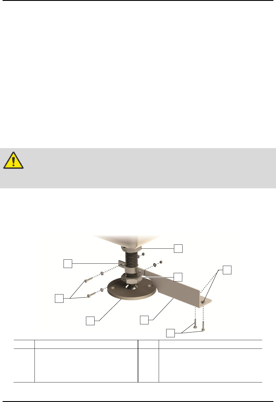
4. Remove the four (4) machine-to-crate shipping brackets attached to the pallet using a 1/2-
inch wrench and 9/16-inch wrench (Figure 3-1).
5. Remove the two (2) 1/2-inch hex head screws clamping the four shipping brackets to the
levelers.
Item
Description
Item
Description
1
Foot Restraint Bracket
5
Lag Bolts and Washers
2 Hex Head Screws and Washers 6 Hex Nuts and Washers
3
Leveler (foot)
7
Post Nut
4 Machine-to-Crate Shipping Bracket 8 Lock Nut
Figure 3-1 Removing the Shipping Brackets
1
3
4
8
7
6
2
5
S2-9XXX Series Dispensing System IOM Manual Installation
© 2023 Nordson Corporation 3-3
6. When the four shipping brackets have been removed, slide the forklift forks under the front
of the dispensing system between the levelers (feet). Use the forklift to gently lift the
dispensing system off of the crate.
You may use the shipping crate for future shipping purposes or dispose of according
to local regulations.
Save the shipping brackets. They can be used later for seismically securing the
dispensing system, see 3.11 Anchoring the Dispensing System.
CAUTION! Lift the dispensing system from the front only. Attempting to lift the dispensing
system from the back or sides may cause serious damage. Place forks between
the front feet, making sure that the blades reach from front to back.
WARNING! The dispensing system has a high center of gravity causing sensitivity to tipping.
Use extreme caution when lifting and moving the dispensing system.
7. Move the dispensing system over the location where it will be installed.
NOTE Remove all shrink wrap and packing foam from the system prior to moving it to a
cleanroom. Remove the protective plastic film from the front door, see 3.6 Unpacking the
Dispensing Chamber. If necessary, clean the system thoroughly.
8. Slowly lower the forklift until the dispensing system conveyor rail is at the approximate
height of the mating upstream and downstream equipment.
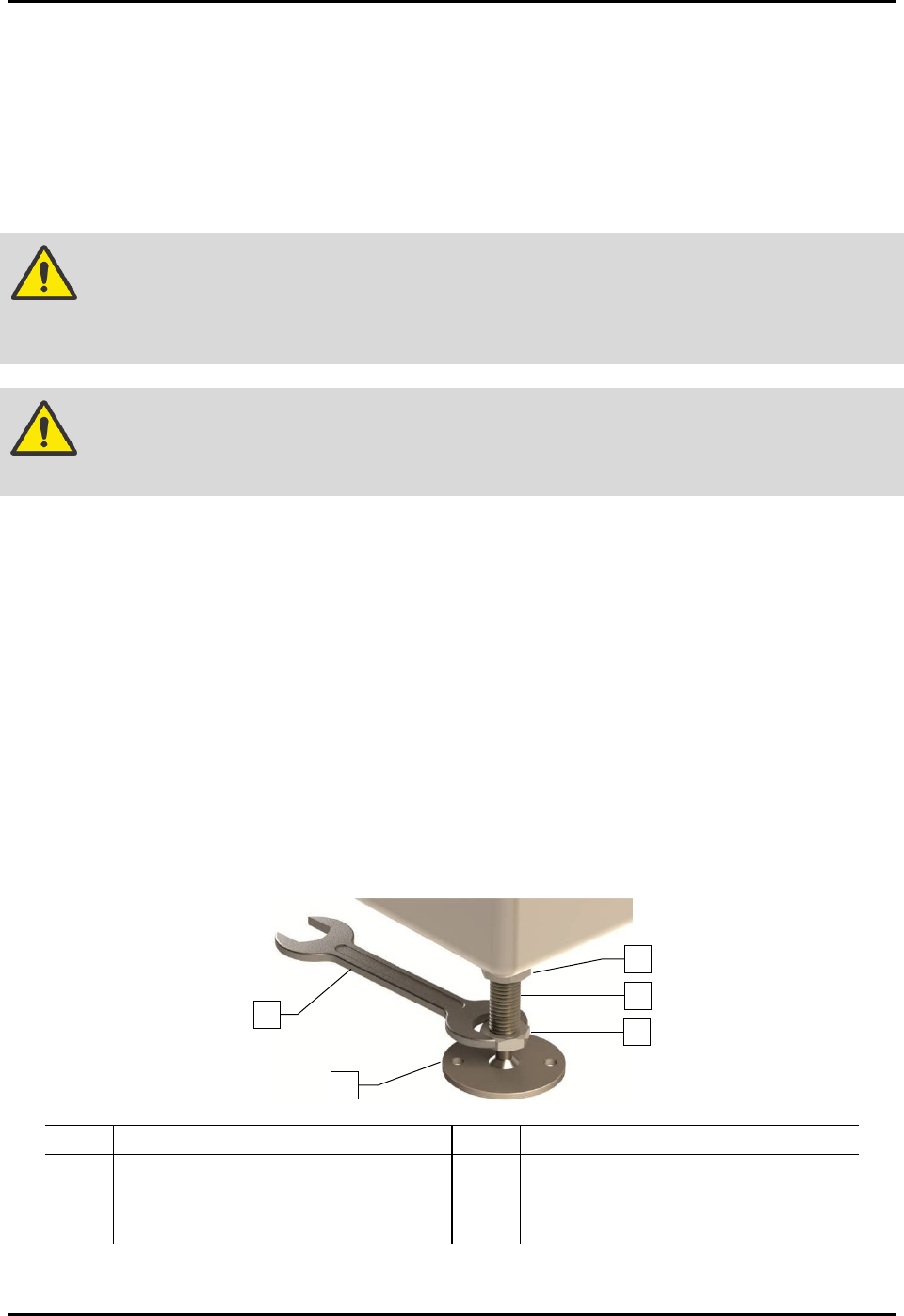
9. Raise or lower each leveler (foot) as follows until they all touch the floor:
a. Loosen the 1 1/2-inch lock nut on the leveler (Figure 3-2).
b. Adjust the 1 1/2-inch post nut to raise or lower each leveler as required.
Turning the post nut clockwise raises the leveler. Turning the post nut
counterclockwise lowers the leveler.
c. Tighten the lock nut finger tight.
Item Description Item Description
1 Lock Nut 4 Leveler (foot)
2 Post 5 1 1/2-inch Wrench
3 Post Nut
Figure 3-2 Adjusting the Levelers
1
5
4
3
2

S2-9XXX Series Dispensing System IOM Manual Installation
3-4 © 2023 Nordson Corporation
10. Remove bag and plastic wrap from the machine.
NOTE Location of packaging materials to be removed is indicated by the presence of
red warning tags.
11. Remove all shrink-wrap and other packing material from the perimeter of the dispensing
system.
3.6 Unpacking the Dispensing Chamber
To unpack the dispensing chamber:
1. Remove all perimeter packaging material from the dispensing area.
2. Remove all tie wraps, tape, foam packing material, and warning tags from the following
areas:
• Dispensing Head
• Conveyor
• Service Station
NOTE Location of packaging materials to be removed is indicated by the presence of
red warning tags. The amount, type, and arrangement of packaging materials
will depend on your system’s configuration.
3. Use a 3 mm hex key to loosen the setscrews on the X- and Y-axis dispensing head stoppers.
4. Remove the stoppers and retain them in a safe place.
5. Remove the shipping bracket and warning tag attached to the Z-head by loosening the
three (3) screws.
Retain bracket and hardware for future shipping purposes.
NOTE The camera is installed and connected at the factory prior to shipping.
6. Remove the tape covering the service station and lid.
7. Remove the front cover by first removing the two screws from the ends of the cover
(Figure 3-3).
8. Lift the cover up and away from the machine.