Spectrum+Operating+Manual.pdf - 第91页
S2-9 XXX Se ri es Dispensing Sys te m IOM Man ual Calibration and Adjustme nt © 2023 Nordson C orporatio n 5-15 4. Co nne ct the external pressu re gauge to th e desired co nnection (val ve, f luid, or cooling) o n t he …
S2-9XXX Series Dispensing System IOM Manual Calibration and Adjustment
5-14 © 2023 Nordson Corporation
5.9 Calibrating the E/P Controllers
If the dispensing system is configured with the optional electronic pressure control utility, follow the
procedure below to calibrate the E/P controllers. During the calibration process, you will ensure that the
Fluidmove pressure set point and Fluidmove pressure reading matches the external pressure gauge
reading.
NOTE This procedure assumes that the dispensing system is ON and Fluidmove is running.
Tools and Materials Needed:
• External Pressure Gauge
• Quick Disconnect Fitting
To calibrate the Fluidmove set point with the external gauge reading:
1. In the Fluidmove Main Window, select
Configuration > Setup Runtime Preferences >
Local Machine Offsets
.
The Local Machine Offsets window opens.
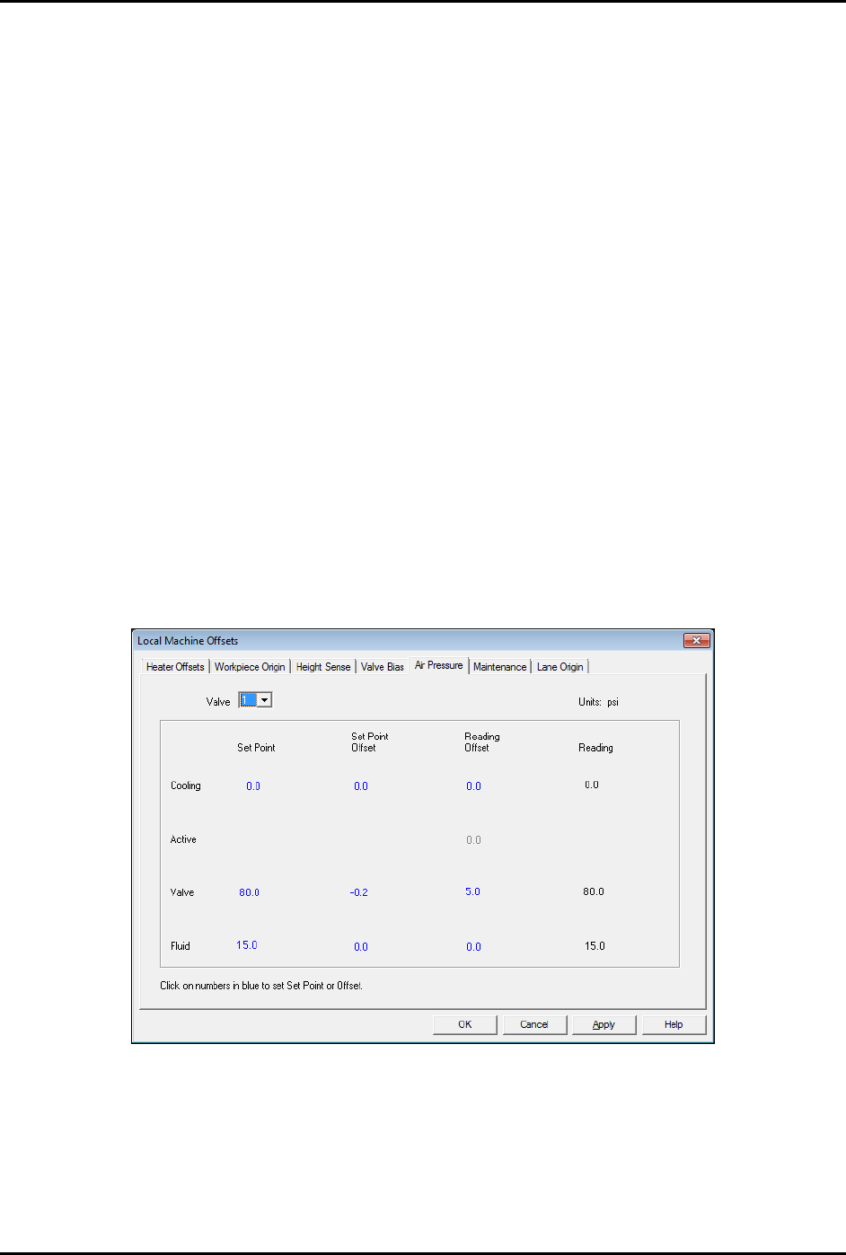
2. Select the Air Pressure tab (Figure 5-15).
This tab displays the Set Point, Set Point Offset, Reading Offset and Reading for
cooling, valve, and fluid pressure. The value in the “Reading” column is the same as the
value in the Current Pressure window (Figure 5-17) accessed by pressing [Ctrl + P] on
the dispensing system keyboard.
Figure 5-15 Local Machine Offsets - Air Pressure Tab
3. To establish air pressure set points, click on the numbers in blue, enter the desired values
and press enter. Click on
OK.
It is best to calibrate valve air pressure with the same pressure setting that will be used
in the dispensing program. It is not necessary for cooling and fluid pressure adjustment.
S2-9XXX Series Dispensing System IOM Manual Calibration and Adjustment
© 2023 Nordson Corporation 5-15
4. Connect the external pressure gauge to the desired connection
(valve, fluid, or cooling) on the dispensing system bulkhead
(Figure 5-16) using a quick disconnect fitting.
For the valve pressure reading, insert the external pressure
gauge hose into the black Valve 1 Off connection on the
bulkhead. If there is no reading, connect the hose to the
blue Valve 1 ON connection.
You should now have a reading at the digital gauge.
5. Compare the external gauge pressure reading to the set point
displayed on the Air Pressure tab (Figure 5-15).
Figure 5-16 Dispensing
System Bulkhead
6. If the pressure reading on the external pressure gauge does not match the software set
point, click on the value in the "Set Point Offset" column and enter the difference between
the actual output (reading on the external gauge) and the set point on the Air Pressure tab.
Click on
Apply. A positive value will increase the output, and negative value will lower
the output. For example, if the gauge reading is 80.2 and the software set point is 80.0,
enter -0.2 in the “Set Point Offset” column. The external gauge output should now be 80.0.
After the set point has been calibrated, it is necessary to calibrate the external pressure
gauge to the software reading.
To calibrate the Fluidmove current pressure reading to the external gauge reading:
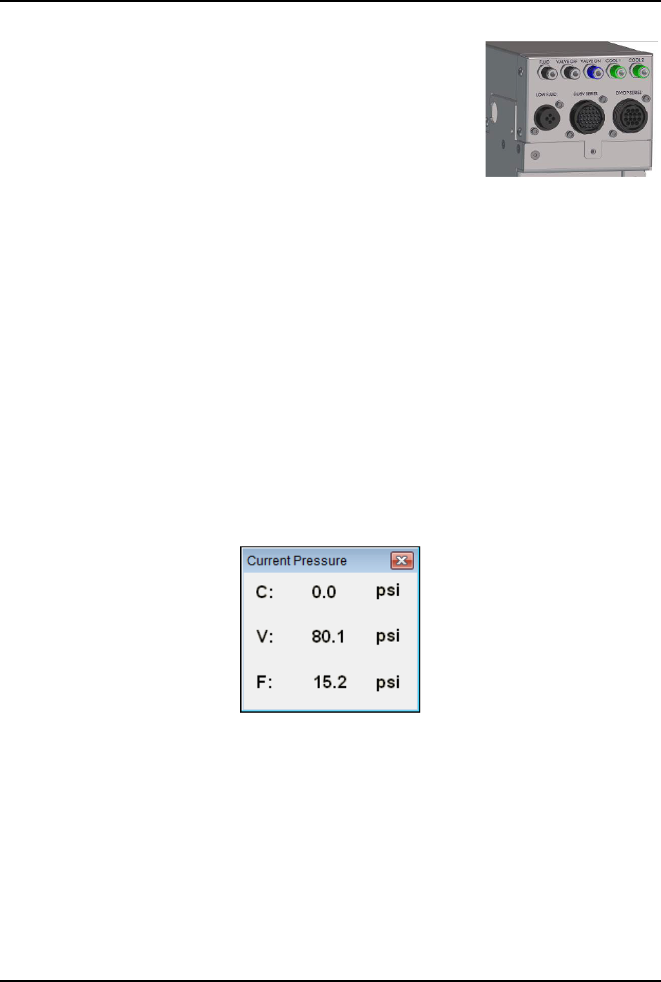
1. Press [Ctrl + P] on the dispensing system keyboard to open the Current Pressure window
(Figure 5-17).
The current pressure is the same as the pressure shown in the “Reading” column on the
Air Pressure tab in the Local Machine Offsets window (Figure 5-15).
Figure 5-17 Current Pressure Window
2. If the reading on the external gauge does not match the current pressure reading in the
software, click on the value in the “Reading Offset” column (Figure 5-15) and enter the
difference between the actual output (reading on the digital gauge) and the reading on the
Air Pressure tab. Click on
Apply.
A positive value will increase the reading, and negative value will lower the reading.
For example, if the gauge reading is 80.0 and the software reading is 75.0, enter 5.0 in
the Reading Offset column. The software reading will change to 80.0.
3. When all applicable outputs have been calibrated, click
OK in the Local Machine Offsets
Window. The values are now set and the E/P controllers are calibrated.
S2-9XXX Series Dispensing System IOM Manual Calibration and Adjustment
5-16 © 2023 Nordson Corporation
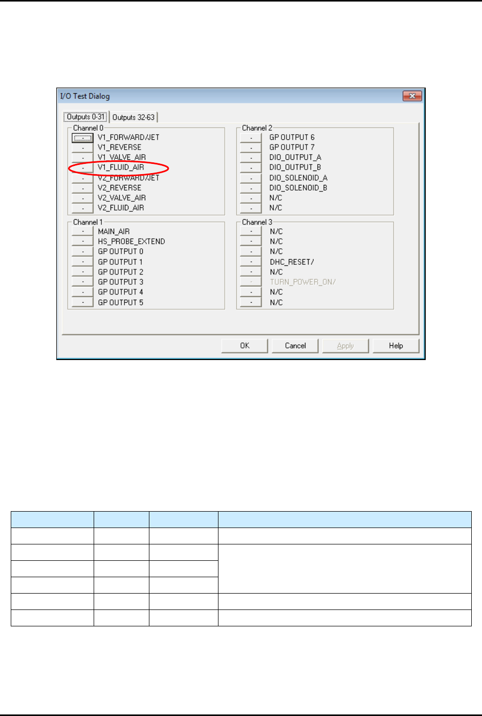
NOTE If the fluid pressure does register on the digital gauge, you must manually
enable the fluid pressure output by selecting
Tools>Dispenser from the
Fluidmove Main Window and toggling the Valve 1 Fluid Air (V1_Fluid_Air)
(Figure 5-18).
Figure 5-18 I/O Test Dialog
5.10 Adjusting the Air Pressure
5.10.1 Air Regulators and Gauges
Air pressure is set manually at the regulator or in the Fluidmove software if the E/P (electronically controlled
pneumatic) regulators option is installed.
Refer to the Fluidmove User Guide or Fluidmove Online Help for
instructions on using the E/P option.
Table 5-2 Manual or E/P Option
Air Pressure Manual E/P Option
Main Air Yes No See 3.13 Adjusting the Main Air Pressure.
Coax/Cooling Yes Yes
See 5.10.3 Adjusting the Cooling/Coaxial, Valve, and
Fluid Air Pressure.
Valve Air Yes Yes
Fluid Air Yes Yes
Lift Table Yes No See 5.10.2 Adjusting the Tooling Air Pressure.
Heater Yes No See 5.14 Calibrating the Heaters.