Spectrum+Operating+Manual.pdf - 第89页
S2-9 XXX Se ri es Dispensing Sys te m IOM Man ual Calibration and Adjustme nt © 2023 Nordson C orporatio n 5-13 7. I f the thresho ld va lue is not in the rang e of the pr esent/not pr esent values, foll ow th e st eps b…
S2-9XXX Series Dispensing System IOM Manual Calibration and Adjustment
5-12 © 2023 Nordson Corporation
5.8 Adjusting the Board Sensors
Board sensors are optical sensors located along the length of the front conveyor rail. The sensors detect
the presence of the workpiece and report it to the conveyor controller. Board sensor sensitivity should be
adjusted after initial installation and if the sensors fail to sense the presence of a workpiece. Depending on
whether the system has a single-lane or dual-lane conveyers, there may be as many as six downward-
facing board sensors (pre-dispense, dispense, and post-dispense station for each conveyor). Sensitivity
adjustments for downward-facing board sensors are made on fiber optic amplifiers mounted under the
dispensing area front cover.
5.8.1 Standard Operation and Tuning
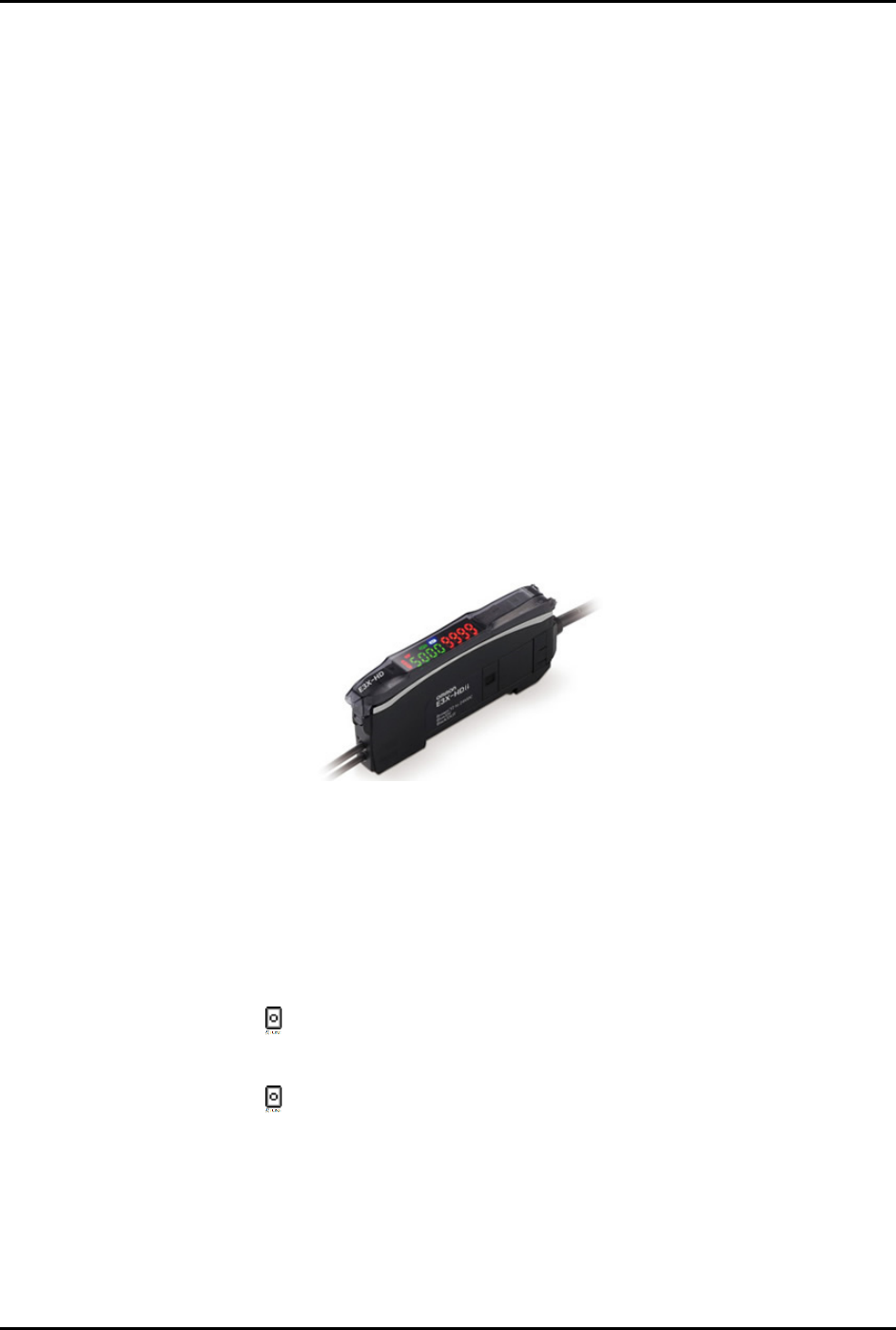
To install the board sensor (Figure 5-13):
1. Unlock the fiber lock (UP position). Insert ferrule ends until the fiber cords are fully seated.
Lock the fiber lock down into position on the conveyor rail.
NOTE Fiber ends are not designated as send or receive. Each ferrule can be used in
either amplifier position.
2. Verify that the digital value of the amplifier is less than 100 with the fiber array pointed
away from any objects (within 6 inches). This ensures array “cross-talk” will not
significantly degrade the signal.
Figure 5-13 E3X-HD Board Sensor
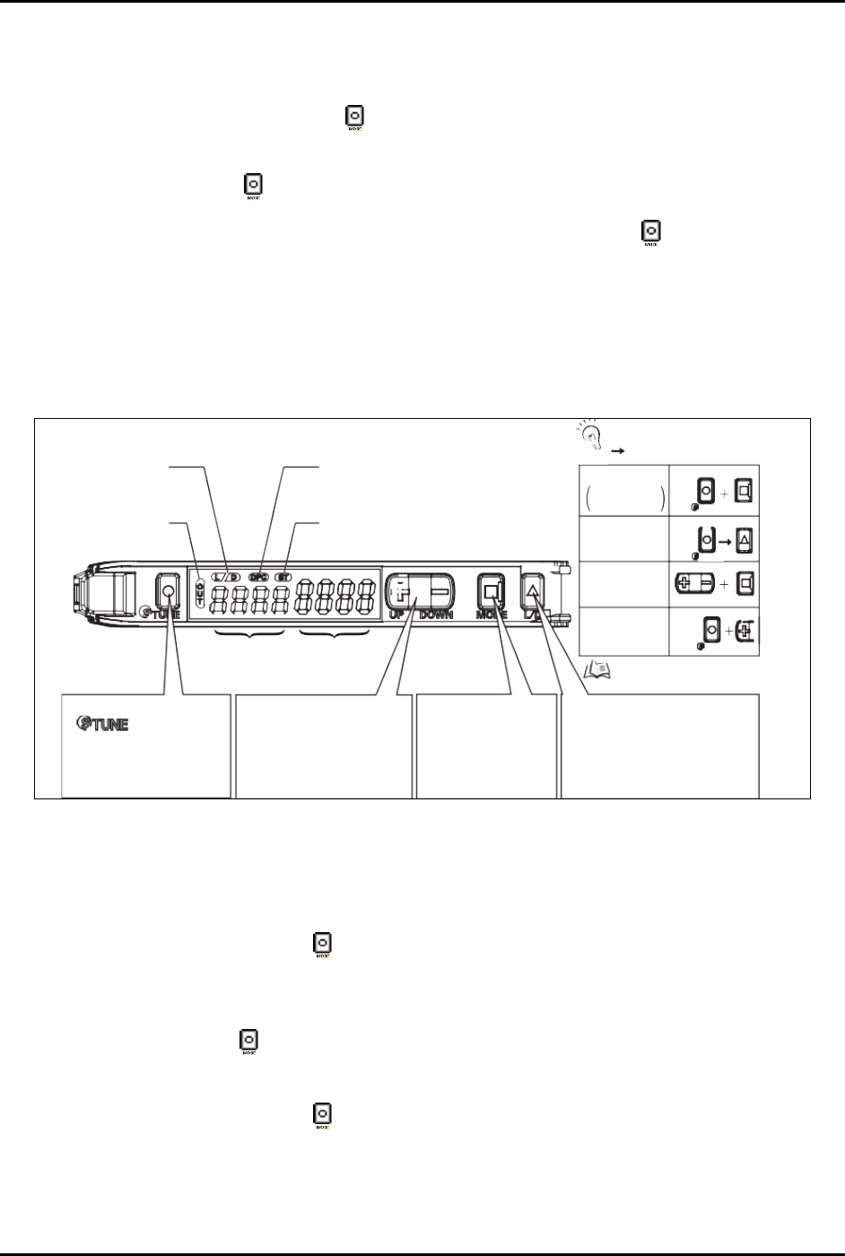
To adjust for workpiece presence/absence (Figure 5-14):
NOTE The E3X-HD 11 sensor requires only one button; place the part/board over the sensor and
push
STune and then move the part/board away from the sensor and push STune again.
1. With the dispensing system on and the fiber installed into the amplifier, place the
carrier/board on the conveyor so that it is breaking the fiber optic sensor beam.
2. Press the
STune button once.
3. Move the carrier/board so that it is clear of the fiber optic sensor beam.
4. Press the
STune button again.
5. Ensure the threshold level (number in red after inverting display, green if normal display) is
between the board present/not present range.
6. If the threshold number is in range, standard tuning is complete.
S2-9XXX Series Dispensing System IOM Manual Calibration and Adjustment
© 2023 Nordson Corporation 5-13
7. If the threshold value is not in the range of the present/not present values, follow the steps
below to adjust the light level. Step 7a through Step 7e are only required if the board sensor
does not respond correctly after adjustment.
a. Press and hold the
Mode button for 3 seconds until [Func dFLt] (or [Func oPt])
begins to blink on the display.
b. Click
Mode button once. You will see [HS] followed by a number.
c. Click the (
+) button until you see [Stnd]. Press and hold Mode until the two sets of
numbers appears again.
d. If the threshold number is still not within the range of values, repeat Step 7b and
Step 7c, but this time click the (
+) button until you see [GIGA].
e. If threshold is still not within range, the fiber optic sensor will need to be moved closer
to the carrier/board.
Power Tuning
When Light
Level is
Saturated
Setting Reset
Key Lock
Zero Reset
MODE
MODE
L/D
UP/DOWN
[DPC Indicator]
Turns ON when Dynamic Power Control is
effective.
[ST Indicator]
Turns ON when Smart Tuning is in progress.
Refer to “Convenient
Setting Features”.
TUNE
TUNE
TUNE
Output Switch
[LD] Button
A single press switches between
Light ON/Dark ON. [L/D] indicator
changes.
Mode Change
[MODE] Button
Switches between SET
mode and RUN mode by
a long press (3 seconds
or longer) of the key.
Sensitivity Setting
[
] Button
A single press for each setting
with/without a workpiece.
[ST Indicator] turns ON.
Minute Threshold
Adjustment
[UP/DOWN] Button
The green digital value changes.
Threshold Level
Green Digital Display
Incident Light
Level
Red Digital Display
[LD Indicator]
Displays
Light ON/Dark O setting.
[OUT Indicator]
Turns ON when Output is
ON.
+
: Press both
: Press both in sequence
UP
CHECK!
Figure 5-14 Board Sensor Setting and Display Overview
5.8.2 Inverting the Display
To invert the display (Figure 5-14):
1. Press and hold the
Mode button for 3 seconds until [Func dFLt] begins to blink on the
display.
2. Click the
Up (+) button once so that [Func oPt] appears.
3. Press the
Mode button until [rEv oFF] is shown.
4. Click the
Up (+) button once so that [rEv on] appears.
5. Press and hold the
Mode button for 3 seconds until the two sets of numbers appear.
After inverting the display, the above diagram will be reversed; the green numbers will
represent the current light level and the red numbers will represent the threshold.
S2-9XXX Series Dispensing System IOM Manual Calibration and Adjustment
5-14 © 2023 Nordson Corporation
5.9 Calibrating the E/P Controllers
If the dispensing system is configured with the optional electronic pressure control utility, follow the
procedure below to calibrate the E/P controllers. During the calibration process, you will ensure that the
Fluidmove pressure set point and Fluidmove pressure reading matches the external pressure gauge
reading.
NOTE This procedure assumes that the dispensing system is ON and Fluidmove is running.
Tools and Materials Needed:
• External Pressure Gauge
• Quick Disconnect Fitting
To calibrate the Fluidmove set point with the external gauge reading:
1. In the Fluidmove Main Window, select
Configuration > Setup Runtime Preferences >
Local Machine Offsets
.
The Local Machine Offsets window opens.
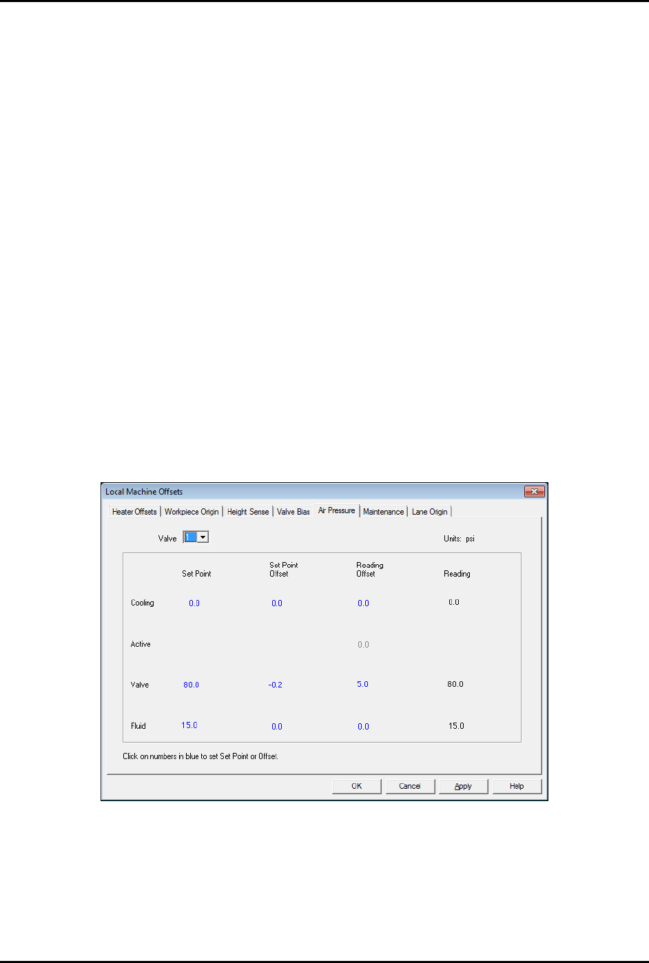
2. Select the Air Pressure tab (Figure 5-15).
This tab displays the Set Point, Set Point Offset, Reading Offset and Reading for
cooling, valve, and fluid pressure. The value in the “Reading” column is the same as the
value in the Current Pressure window (Figure 5-17) accessed by pressing [Ctrl + P] on
the dispensing system keyboard.
Figure 5-15 Local Machine Offsets - Air Pressure Tab
3. To establish air pressure set points, click on the numbers in blue, enter the desired values
and press enter. Click on
OK.
It is best to calibrate valve air pressure with the same pressure setting that will be used
in the dispensing program. It is not necessary for cooling and fluid pressure adjustment.