Spectrum+Operating+Manual.pdf - 第98页
S2-9 XX X Se ri es Disp ensi n g Syst em IOM Man ual Calibration and Adjustme nt 5-22 © 2023 Nordson Corporatio n Figure 5- 27 A Dispe nsin g Head with Mec hanical/Tac ti le Height S e nsor Figure 5- 27 B Probe - to - No…
S2-9XXX Series Dispensing System IOM Manual Calibration and Adjustment
© 2023 Nordson Corporation 5-21
5.12 Adjusting the Height Sensor Probe (Option)
The height sensor probe must be adjusted each time a different type of dispensing valve or a different
length of needle is installed.
To adjust the height sensor probe (mechanical/tactile height sensor):
1. Power on the dispensing system, see 4.3 Powering on the Dispensing System.
2. Start the Fluidmove software. Refer to the Fluidmove User Guide or Fluidmove Online
Help.
3. Select
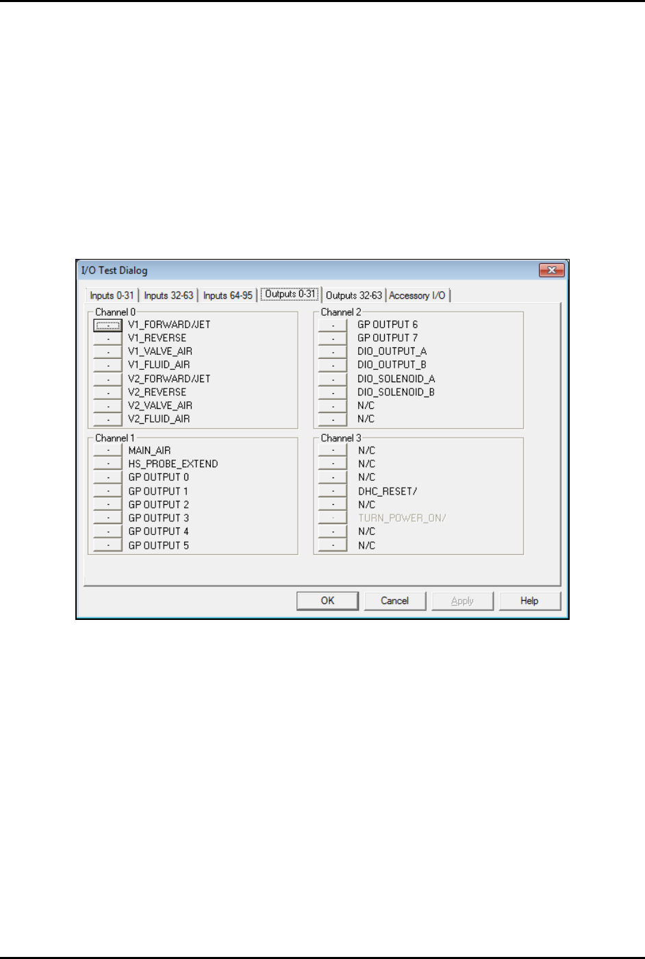
Tools > I/O Test > Dispenser from the Fluidmove Main Menu.
The I/O Test Dialog window opens (Figure 5-26).
Figure 5-22 I/O Test Dialog
4. Click on HS_PROBE_EXTEND to extend the height sensor probe.
The bit should change from 0 to 1.
5. Manually move the dispensing head down to provide access to the height sensor
locking screws.
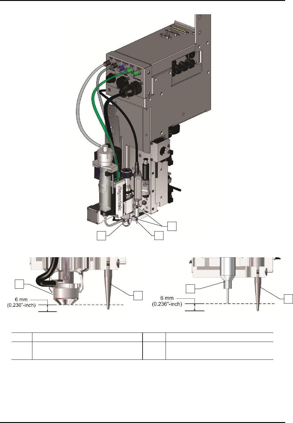
6. Loosen the two (2) height sensor locking screws (Figure 5-27A).
7. Move the probe to the desired location; approximately 6 mm below the nozzle or needle tip
in the gear down position (Figure 5-27B and Figure 5-27C).
8. Do not over-tighten, tighten the two (2) height sensor locking screws.
S2-9XXX Series Dispensing System IOM Manual Calibration and Adjustment
5-22 © 2023 Nordson Corporation
Figure 5-27A Dispensing Head with Mechanical/Tactile Height Sensor
Figure 5-27B Probe-to-Nozzle Alignment
Figure 5-27C Probe-to-Needle Alignment
Item
Description
Item
Description
1 Nozzle 3 Height Sensor Locking Screws (2)
2
Height Sensor Probe
4
Needle
Figure 5-23 Adjusting the Height Sensor Probe
2
1
3
2
1
2
4
S2-9XXX Series Dispensing System IOM Manual Calibration and Adjustment
© 2023 Nordson Corporation 5-23
5.13 Initializing the Digital Gauges
The S2-9XX and the S2-9XX/A Series Dispensing Systems are equipped with cooling/coaxial, valve and
fluid pressure digital gauges. If the dispensing system is configured with the optional E/P utility, the digital
gauges will not be present.
To initialize the digital gauge:
1. Make sure the air pressure to the pressure gauge is OFF by turning the appropriate regulator
knob counterclockwise until it stops (Figure 1-9).
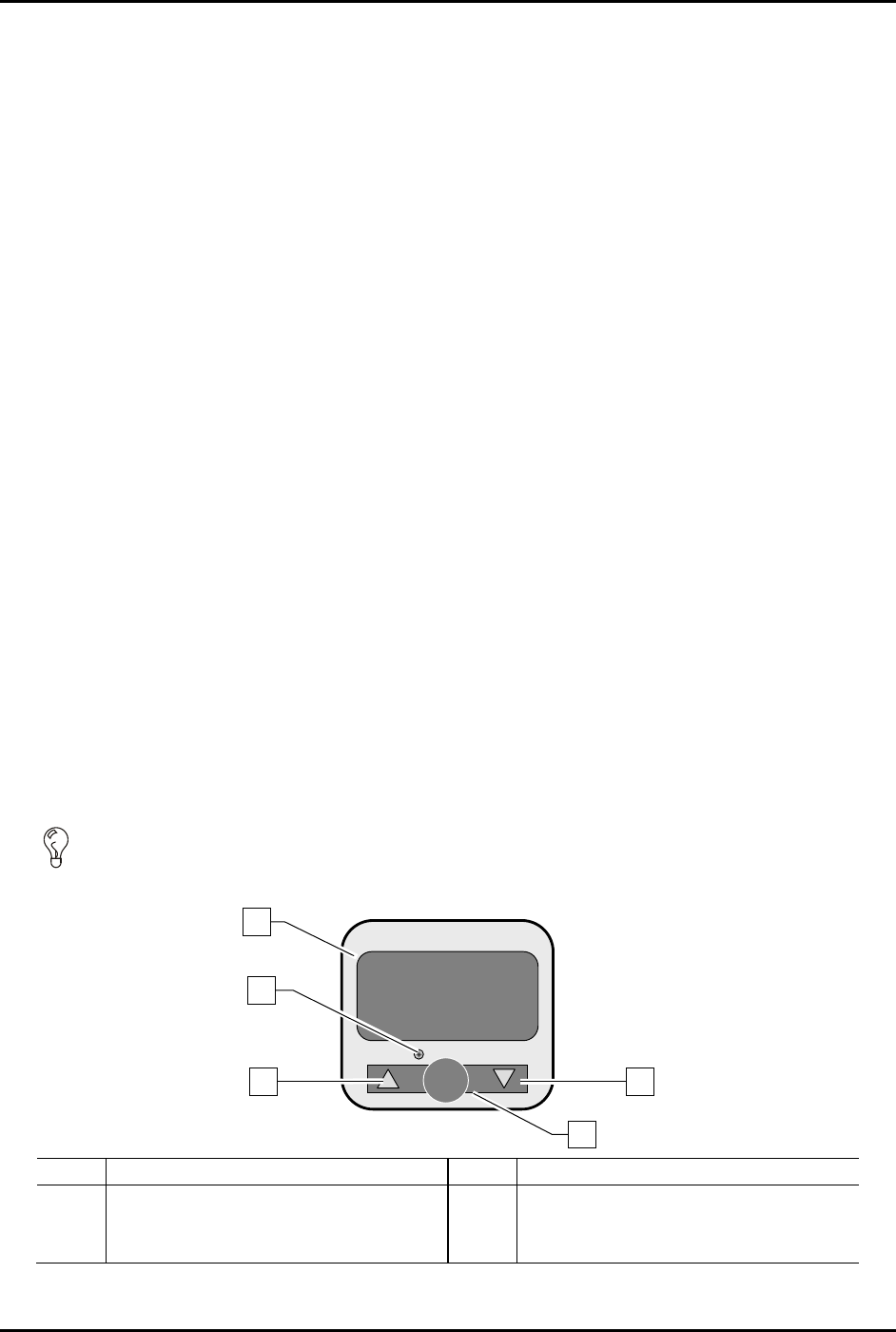
2. To configure the gauge, press and hold down the
SET button for at least two (2) seconds
(Figure 5-28).
3. Select the measuring unit by pressing the
Up button or Down button until the desired
measuring unit is displayed and then press
SET.
Available units are kPa or MPa (PA), kgf/cm2 (GF), bar (bAr), and psi (PSi).
4. Verify the Output 1 type is set on the normally open (1no) setting. If it is not displayed,
press the Up or Down button until 1no is displayed and then press
SET.
NOTE The output function of the digital gauge is not used on your dispensing system.
5. Verify the response time is set at 192 ms. If it is not displayed, press the
Up or Down button
until 192 is displayed.
6. Verify the setting mode is set on the manual setting (nAn). If the manual setting is not
displayed, press the
Up or Down button until nAn is displayed and then press SET.
The gauge will now be in the pressure-measuring mode.
7. Zero the gauge by holding down both arrow buttons simultaneously until zeros (00.0) are
displayed on the screen.
8. Set the pressure to the desired level for your application by turning the knob on the pressure
regulator knob clockwise until the correct pressure is displayed on the screen.
TIP To ensure accurate pressure measurement, allow the gauge to warm up for 20 to 30
minutes before adjusting pressure level.
35.4
OUT 1
SET
SMC
MPa
PRESSURE
Item
Description
Item
Description
1
LED Display
4
Set Button
2
Switch Output Indicator
5
Down Button
3
Up Button
Figure 5-24 Initializing the Digital Gauge
1
2
3
4
5