Spectrum+Operating+Manual.pdf - 第177页
S2-9 XXX Se ri es Dispensing Sys te m IOM Man ual Parts Replacement © 2023 Nordson C orpor ation 8-25 8.15 Replacing Control Pan el Components Tools and Materials Needed : • Hex Key Set (Item 59) WA RNIN G! T he control …

S2-9XXX Series Dispensing System IOM Manual Parts Replacement
8-24 © 2023 Nordson Corporation
6. Reinstall any removed stop pins to their former positions.
7. Close the dispensing area door.
8. When both conveyor belts have been replaced, power on the dispensing system, see
4.3 Powering on the Dispensing System.
9. Click on both the left and right conveyor belt jog buttons to move the conveyor belts in both
directions.
The conveyor belts should move smoothly in both directions with no slipping on their
pulleys.
10. If necessary,
tension the conveyor belts, see 6.13 Tensioning the Conveyor Belts.
S2-9XXX Series Dispensing System IOM Manual Parts Replacement
© 2023 Nordson Corporation 8-25
8.15 Replacing Control Panel Components
Tools and Materials Needed:
• Hex Key Set (Item 59)
WARNING! The control panel must be supported during removal as there are cable
connections from the dispensing system to the control panel. Not supporting the
control panel may cause wiring and connector damage.
WARNING! Ensure the dispensing system has been completely shutdown before attempting to
remove any panel.
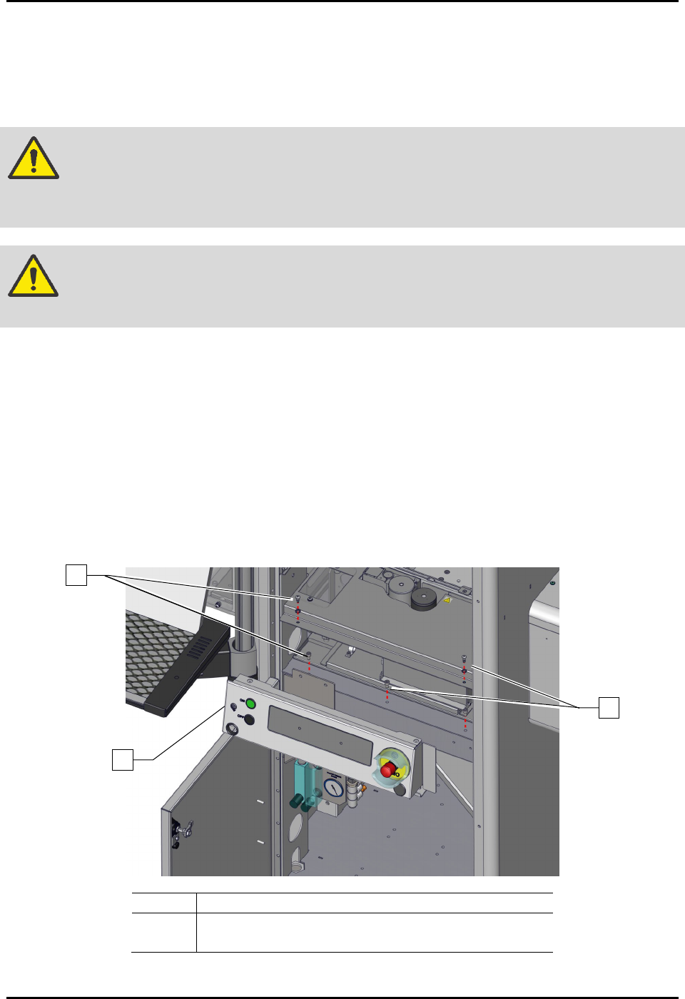
8.15.1 Removing and Installing the Control Panel
To remove the control panel (Figure 8-20):
1. Perform a service shutdown, see 2.14 Service Shutdown.
2. Open the dispensing area door.
3. Remove the dispense station cover, see 8.8 Removing and Installing the Dispense Station
Cover.
4. Remove the four (4) screws securing the control panel to the dispensing system.
5. Remove the control panel.
Item
Description
1
Control Panel
2
Screws (4)
Figure 8-20 Replacing the Control Panel (Wiring Not Shown for Clarity)
1
2
2

S2-9XXX Series Dispensing System IOM Manual Parts Replacement
8-26 © 2023 Nordson Corporation
To install the control panel (Figure 8-20):
1. If necessary, replace the failed switches, see 8.13.2 Replacing the Front EMO Actuator
Switch, 8.13.3 Replacing the ON Switch, or 8.13.4 Replacing the OFF Switch.
2. Install the control panel onto the dispensing system.
Make sure to support the control panel or wiring and cable connector damage may
occur.
3. Install the four (4) screws securing the control panel to the dispensing system.
4. Replace the dispense station cover, see 8.8 Removing and Installing the Dispense Station
Cover.
5. Close the dispensing area door.