Spectrum+Operating+Manual.pdf - 第168页
S2-9 XX X Se ri es Disp ensi n g Syst em IOM Man ual Parts Replacement 8-16 © 2023 Nordson Corporatio n To install the LED light ( Figu re 8- 12 ): 1. Install the LED light into the LED len s clips. 2. Connect the electr…
S2-9XXX Series Dispensing System IOM Manual Parts Replacement
© 2023 Nordson Corporation 8-15
8.13 Replacing Components Inside the Dispensing Area
Door
Tools and Materials Needed:
• Hex Key Set (Item 59)
• Torque Wrench
• Adjustable Wrench
WARNING! Ensure the dispensing system has been completely shutdown before attempting
to remove or install any panel, electrical component, or pneumatic component.
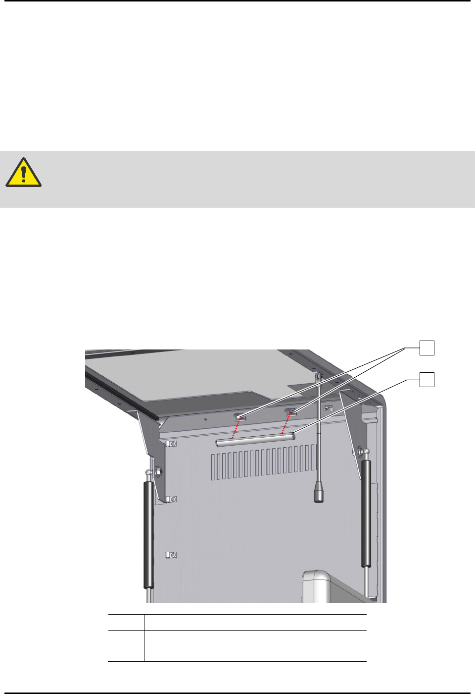
8.13.1 Replacing the LED Light
To remove the LED light (Figure 8-12):
1. Perform a service shutdown, see 2.14 Service Shutdown.
2. Open the dispensing area door.
3. Disconnect the electrical connection to the LED light.
4. Remove the LED light from the LED lens clips.
Item
Description
1 LED Lens Clips
2 LED, Lens, Clips, Kit, 12V, 6” (Item 45)
Figure 8-12 Replacing the LED Light (Wiring Not Shown for Clarity)
1
2
S2-9XXX Series Dispensing System IOM Manual Parts Replacement
8-16 © 2023 Nordson Corporation
To install the LED light (Figure 8-12):
1. Install the LED light into the LED lens clips.
2. Connect the electrical connection to the LED light.
3. Close the dispensing area door.
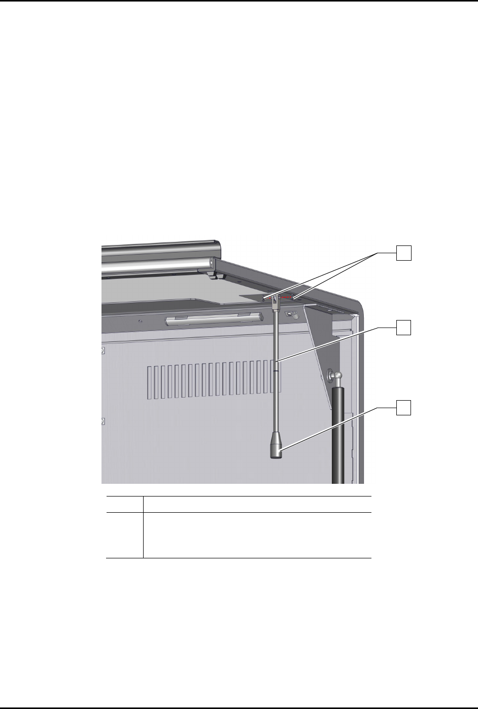
8.13.2 Replacing the Standoff
To remove the standoff (Figure 8-13):
1. Perform a service shutdown, see 2.14 Service Shutdown.
2. Open the dispensing area door.
3. Remove the two (2) C-clips securing the standoff to the dispensing area door.
4. Remove the standoff from the dispensing area door.
Item Description
1
2
C-Clips (2)
Standoff (Item 46)
3
Handle (Item 46)
Figure 8-13 Replacing the Standoff
To install the standoff (Figure 8-13):
1. Install the two (2) C-clips securing the standoff to the dispensing area door.
2. Close the dispensing area door.
3
2
1
S2-9XXX Series Dispensing System IOM Manual Parts Replacement
© 2023 Nordson Corporation 8-17
8.13.3 Replacing the Gas Spring
This procedure is applicable to the left or right spring.
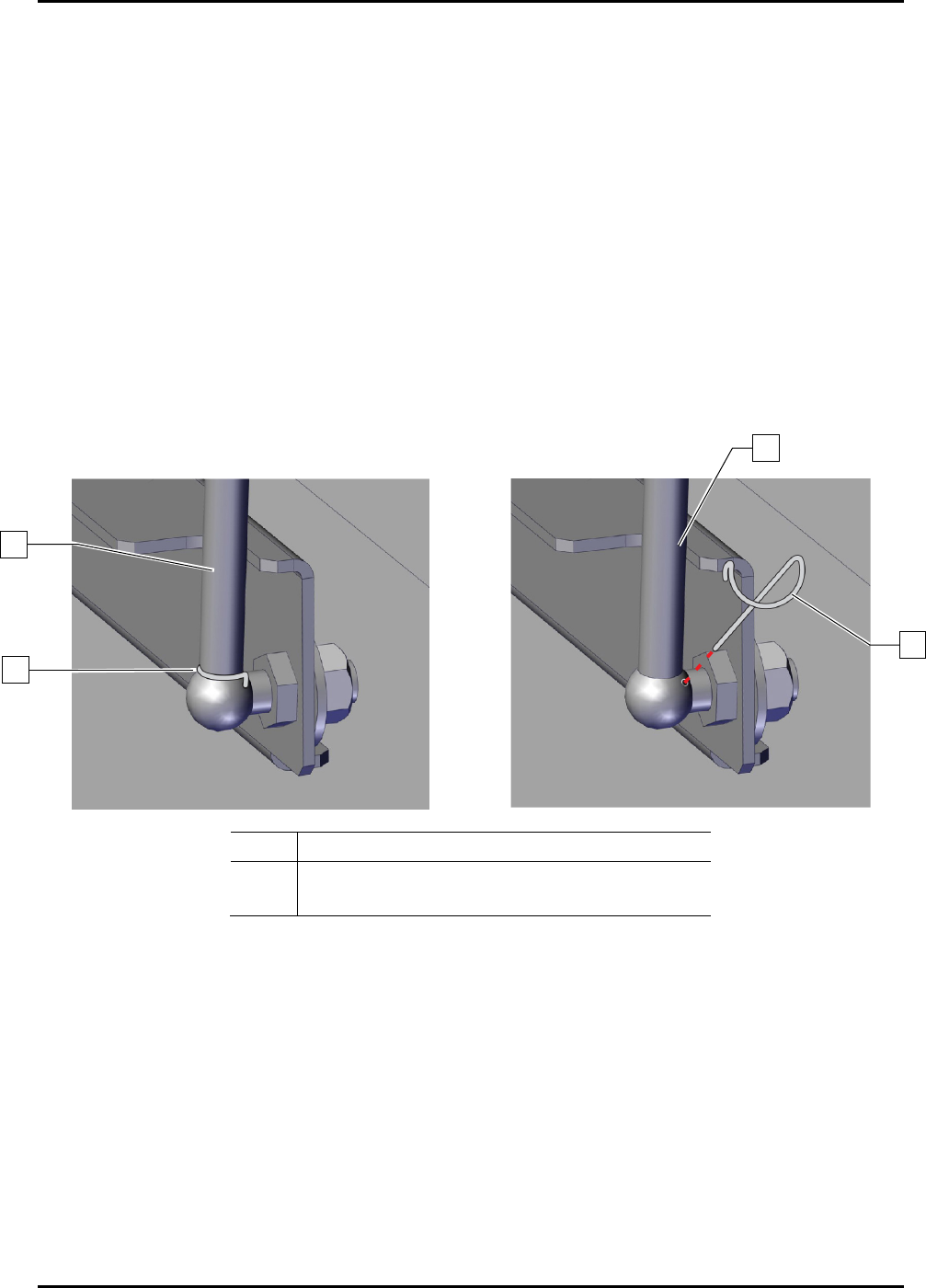
8.13.3.1 Replacing the Gas Spring and Retaining Clip
This procedure assumes that the gas spring has a retaining clip installed. Repeat this procedure for both
the left and right gas spring as necessary. If a retaining clip is not installed, see 8.11.3.2 Replacing the
Gas Spring and Ball Joint.
To remove the gas spring (Figure 8-14):
1.
Perform a service shutdown, see 2.14 Service Shutdown.
2. Open and support the dispensing area door during removal and installation.
3. Remove the retaining clip securing the gas spring to the dispensing system.
Pull up on the gas spring and twist it in the opposite direction.
4. Remove the gas spring.
Item
Description
1
2
Gas Spring
Retaining Clip
Figure 8-14 Replacing the Retaining Clip
To install the gas spring (Figure 8-14):
1. Replace the gas spring.
2. Secure the gas spring with the retaining clip.
Verify that the retaining clip is wrapped around the gas spring.
1
2
2
1