Spectrum+Operating+Manual.pdf - 第182页
S2-9 XX X Se ri es Disp ensi n g Syst em IOM Man ual Parts Replacement 8-30 © 2023 Nordson Corporatio n To install the on switch ( Figu re 8-22): 1. Inst al l the sw itch as semb ly thr o ug h th e fro n t o f the contro…
S2-9XXX Series Dispensing System IOM Manual Parts Replacement
© 2023 Nordson Corporation 8-29
8.15.3 Replacing the ON Switch
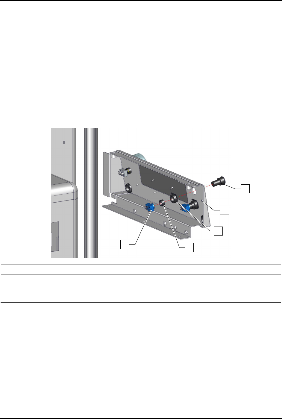
To remove the on switch (Figure 8-22):
1. Perform a service shutdown, see 2.14 Service Shutdown.
2. Remove the control panel, see 8.13.1 Removing and Installing the Control Panel.
3. Disconnect the power control cables from the contact block.
4. Disconnect the contact block from the momentary actuator.
5. From rear of the control panel, use the switch mounting tool to remove the metal mounting
nut securing the metal flush mount adapter.
6. Remove the metal flush mount adapter from the rear of the control panel and the green LED
switch from the front of the control panel.
Item Description Item Description
1 Switch, 3P-NO, Green LED (Item 15) 4 Metal Mounting Nut
2 Control Panel 5 Contact Block (Item 15)
3 Metal Flush Mount Adapter
Figure 8-22 Replacing the ON Switch (Wiring Not Shown for Clarity)
1
2
3
4
5
S2-9XXX Series Dispensing System IOM Manual Parts Replacement
8-30 © 2023 Nordson Corporation
To install the on switch (Figure 8-22):
1. Install the switch assembly through the front of the control panel.
2. Apply one small drop of plastic thread locker onto the threads of the metal mounting nut.
3. Install the metal flush mount adapter and metal mounting nut from the rear of the control
panel onto the switch assembly.
4. Tighten the nut utilizing the switch mounting tool.
5. Connect the contact block to the momentary actuator.
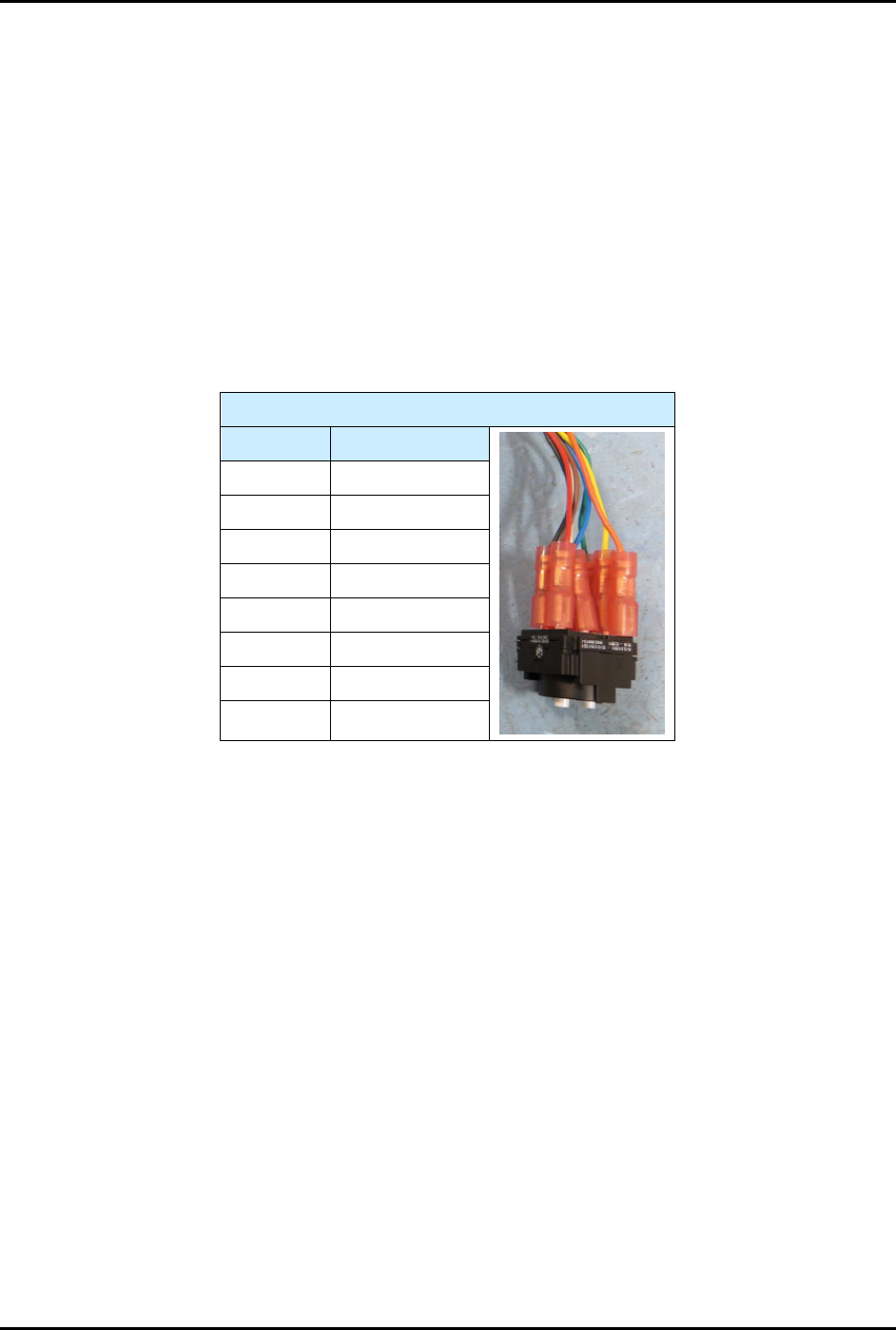
6. Connect the power control cables to the contact block, see Table 8-2.
7. Reinstall the control panel, see 8.13.1 Removing and Installing the Control Panel.
Table 8-2 Power Control Cable Connections (ON Switch)
ON Switch
Contact # Color
13 Black
13 Red
X1 Blue
X2 Brown
23 White
24 Green
33 Yellow
34
Orange
S2-9XXX Series Dispensing System IOM Manual Parts Replacement
© 2023 Nordson Corporation 8-31
8.15.4 Replacing the OFF Switch
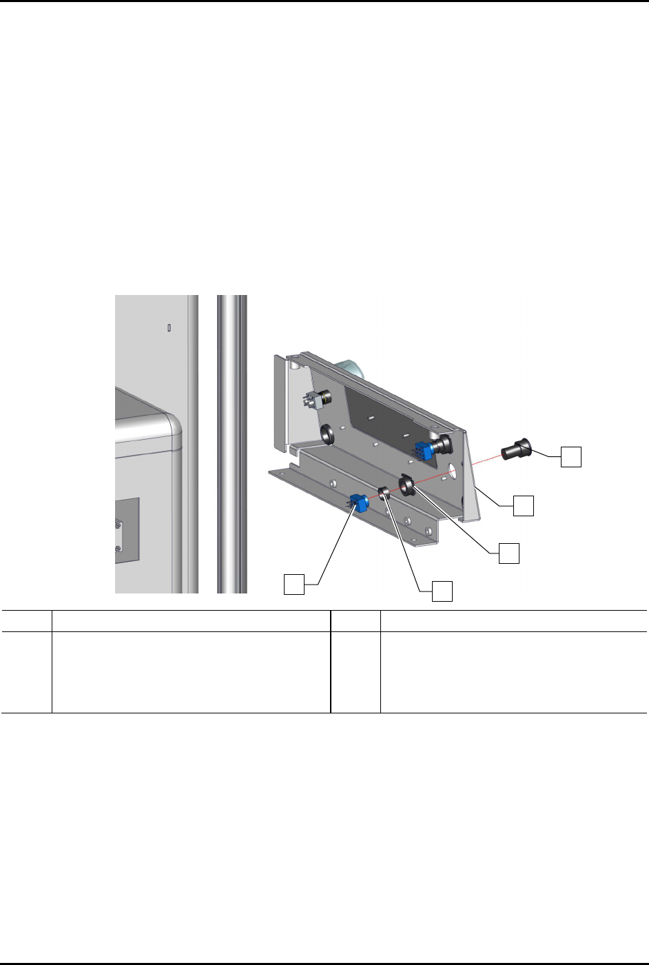
To remove the off switch (Figure 8-23):
1. Perform a service shutdown, see 2.14 Service Shutdown.
2. Remove the control panel, see 8.13.1 Removing and Installing the Control Panel.
3. Disconnect the power control cables from the contact block.
4. Disconnect the contact block from the metal flush mount adapter.
5. From rear of the control panel using the switch mounting tool, remove the nut securing the
metal flush mount adapter.
6. Remove the metal flush mount adapter from the rear of the control panel and the black
switch from the front of the control panel.
Item Description Item Description
1
Switch, 2P-NC, MOM, Black Flush
(Item 15)
4 Metal Mounting Nut
2 Control Panel 5 Contact Block (Item 15)
3 Metal Flush Mount Adapter
Figure 8-23 Replacing the Off Switch (Wiring No Shown for Clarity)
1
2
3
4
5