Spectrum+Operating+Manual.pdf - 第136页
S2-9 XX X Se ri es Disp ensi n g Syst em IOM Man ual Maintenance 6-24 © 2023 Nordson Corporatio n 6.12.3 A djust ing the Z- A xi s Linear Encoder Gap To adjus t the Z -a xis l in ea r e nco der ga p (Figur e 6 - 17 ): 1.…
S2-9XXX Series Dispensing System IOM Manual Maintenance
© 2023 Nordson Corporation 6-23
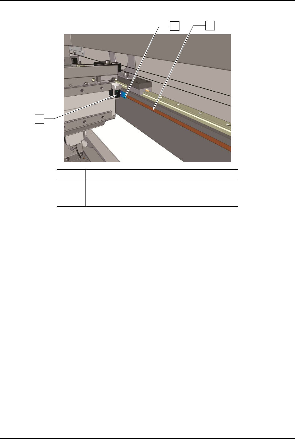
6. Place the 0.8 mm gauge in the space between the linear encoder head and the linear encoder
strip (Figure 6-16).
Item
Description
1 0.8 mm Gauge
2
Encoder Strip
3 Encoder Read Head
Figure 6-16 Adjusting the Y-Axis Linear Encoder Gap
7. Apply thread locker to the hex bolt threads.
8. Press down on the encoder until it is on top of the gauge.
You should be able to slide the gauge back and forth under the encoder. If the gauge
slides too easily the gap may be too wide.
9. Once the correct gap is established, use the 3 mm hex key to tighten the hex bolts and
secure the encoder in place.
10. Remove the gauge from beneath the encoder.
11. Manually move the dispensing head back and forth (front to back) along the full length of
the Y-axis travel. Make sure that the encoder LED remains green throughout the move.
If the LED turns red or orange when the axis is in motion, repeat Step 4 through Step 11
and adjust the encoder height again.
If you notice that the LED turns red or orange in a specific location, it may be due to an
obstruction or a damaged encoder strip. Try using a soft cloth and mild cleanser to clean
that location. If the problem is not resolved, repeat Step 4 through 11 and adjust the
encoder height again.
12. When the LED stays green throughout the entire dispensing head travel, close the
dispensing area door and restart Fluidmove.
13. Observe the dispense head motion to ensure the dispensing head initializes properly and
finds home correctly.
2
1
3
S2-9XXX Series Dispensing System IOM Manual Maintenance
6-24 © 2023 Nordson Corporation
6.12.3 Adjusting the Z-Axis Linear Encoder Gap
To adjust the Z-axis linear encoder gap (Figure 6-17):
1. If necessary, power on the dispensing system, see 4.3 Powering on the Dispensing System.
2. Exit Fluidmove.
3. Open the dispensing area door.
4. Place the 0.8 mm gauge in the space between the linear encoder head and the linear encoder
strip.
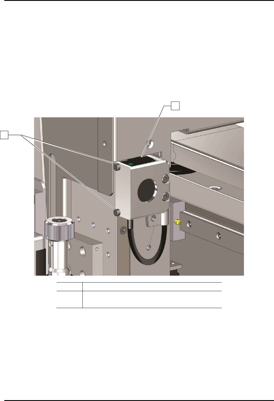
5. To adjust the Z-axis linear encoder gap, use the 3 mm hex key to loosen the two mounting
screws on the encoder bracket.
Item
Description
1 Linear Encoder
2
Encoder Mounting Screws (2)
Figure 6-17 Adjusting the Linear Encoder Height
6. Apply Loctite thread locker to the hex bolt threads.
7. Press the encoder against the gauge. Make sure that the encoder is level and not pinching
the gauge.
You should be able to slide the gauge up and down beneath the encoder. If the gauge
slides too easily, the gap may be too wide.
8. Use the 3 mm hex key to secure the encoder in place.
1
2

S2-9XXX Series Dispensing System IOM Manual Maintenance
© 2023 Nordson Corporation 6-25
9. Remove the gauge from under the encoder.
10. Manually move the dispensing head up and down and make sure that the encoder LED
remains green when in motion.
If the LED turns red or orange when the axis is in motion, repeat Step 4 through Step 11
and adjust the encoder height again.
If you notice that the LED turns red or orange in a specific location, it may be due to an
obstruction or a damaged encoder strip. Try using a soft cloth and mild cleanser to clean
that location. If the problem is not resolved, repeat Step 4 through Step 11 and adjust
the encoder height again.
11. When the LED stays green throughout the entire dispensing head travel, close the
dispensing area door and restart Fluidmove.
12. Observe the dispensing head motion to ensure the dispensing head initializes properly and
finds home correctly.