Spectrum+Operating+Manual.pdf - 第26页
S2-9 XX X Se ri es Disp ensi n g Syst em IOM Man ual Introductio n 1-16 © 2023 Nordson Corpor ation 1.9.6 Fr ont Cabi net S2 - 9XXX Se ri es Systems S2 - 9XXP Series Syst e ms NOT E The S2 - 9 XXP Serie s features prog…
S2-9XXX Series Dispensing System IOM Manual Introduction
© 2023 Nordson Corporation 1-15
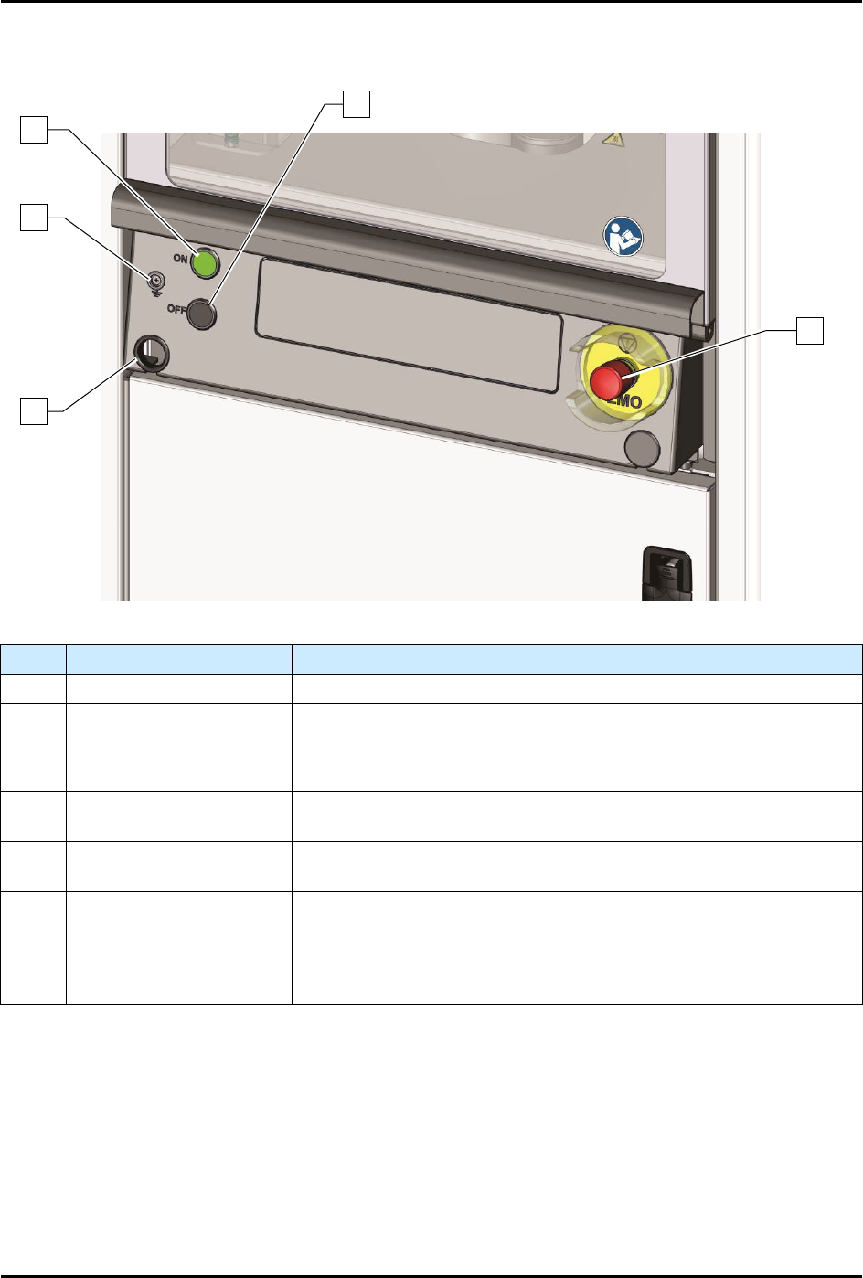
1.9.5 Front Panel
Item Name Description
1 Computer Connection Connects the dispensing system to the laptop computer.
2 Grounding Strap Jack
Grounding straps worn by the operator or technician attach to this
connector. This prevents Electrostatic Discharge (ESD) damage to
workpieces and dispensing system electronics during dispensing
operations and servicing.
3 ON Button
The green ON (l) button illuminates and switches ON power to the
dispensing system mechanics.
4 OFF Button
The black OFF (0) button shuts down the dispensing activity and
vents the air pressure. The computer power remains ON.
5
Emergency Machine Off
(EMO)
Activating the EMO vents all pressure in the pneumatic system, de-
energizes the servo power, and cuts power to all system
components except the computer
. An EMO button is located on the
front and rear of the conformal coating system. See
Section 2 - Safety
for additional information.
Figure 1-8 Front Panel
1
5
4
2
3
S2-9XXX Series Dispensing System IOM Manual Introduction
1-16 © 2023 Nordson Corporation
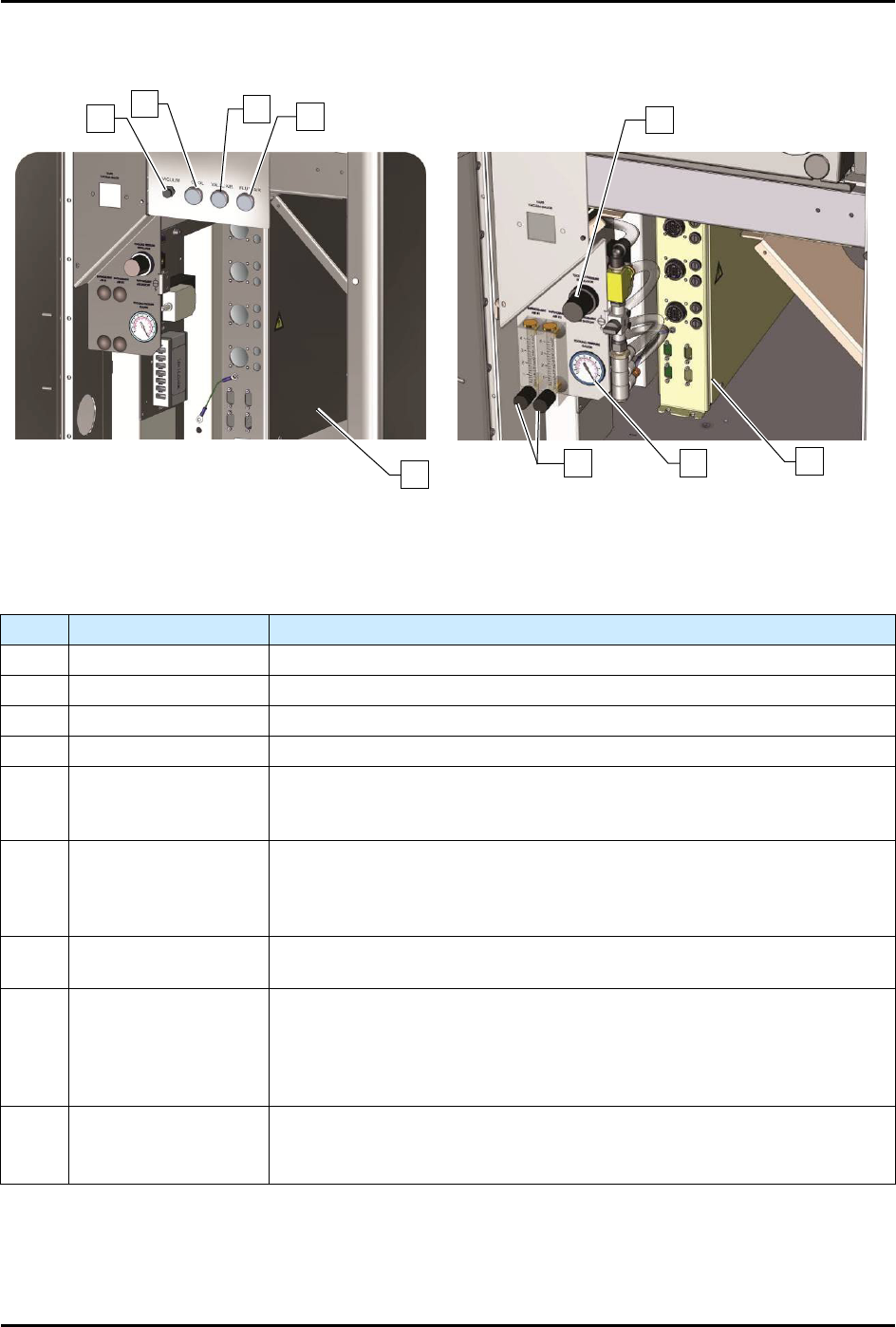
1.9.6 Front Cabinet
S2-9XXX Series Systems
S2-9XXP Series Systems
NOTE The S2-9XXP Series features programmable fluid and valve pressure. Air pressure is set
through the Fluidmove software. This feature is an option on the S2-9XXX Series Systems.
Item
Name
Description
1 Vacuum Air Regulator Controls the air pressure supplied to the vacuum air.
2 Cooling Air Regulator Controls the air pressure supplied to the cooling air.
3 Valve Air Regulator Controls the air pressure supplied to the valve air.
4 Fluid Air Regulator Controls the air pressure supplied to the fluid air.
5
Tooling Pressure
Regulator
Controls the air pressure supplied to the stop pins and lift tables. The
regulator receives air from the main air regulator located on the back of
the dispensing system.
6
Conveyor/Heater
Module (systems with
heat)
Controls all conveyor functions (motors, sensors, pneumatics, etc.). It
receives power from the power manager and supplies AC power to the
substrate heaters in the dispensing area. Dual conveyor systems require
two conveyor/heater modules.
7
Tooling Pressure
Gauge
Displays the air pressure supplied to the stop pins and lift tables.
8
Impingement
Flowmeters*
(S2-9XXP)
Not on S2-9XXC
Controls the airflow through the impingement heaters in the dispensing
chamber. A manual shut-off valve controls the air going to the
flowmeters. Note: Depending on system configuration, a dispensing
system may have up to six (6) flowmeters (pre-dispense, dispense, and
post-dispense for Conveyor 1 and Conveyor 2).
9
Conveyor Controller
Module (systems
without heat)
Controls all conveyor functions (motors, sensors, pneumatics, etc.). If
your system is equipped with dual conveyors, two Conveyor Controller
Modules are required.
Figure 1-9 Front Cabinet
*Impingement flowmeters are standard on the S2-9XXP. The flowmeters may be optionally replaced by
Controlled Process Heat (CpH) software, see 5.15 Controlled Process Heat.
1
2
3
4
9
5
6
7
8
S2-9XXX Series Dispensing System IOM Manual Introduction
© 2023 Nordson Corporation 1-17
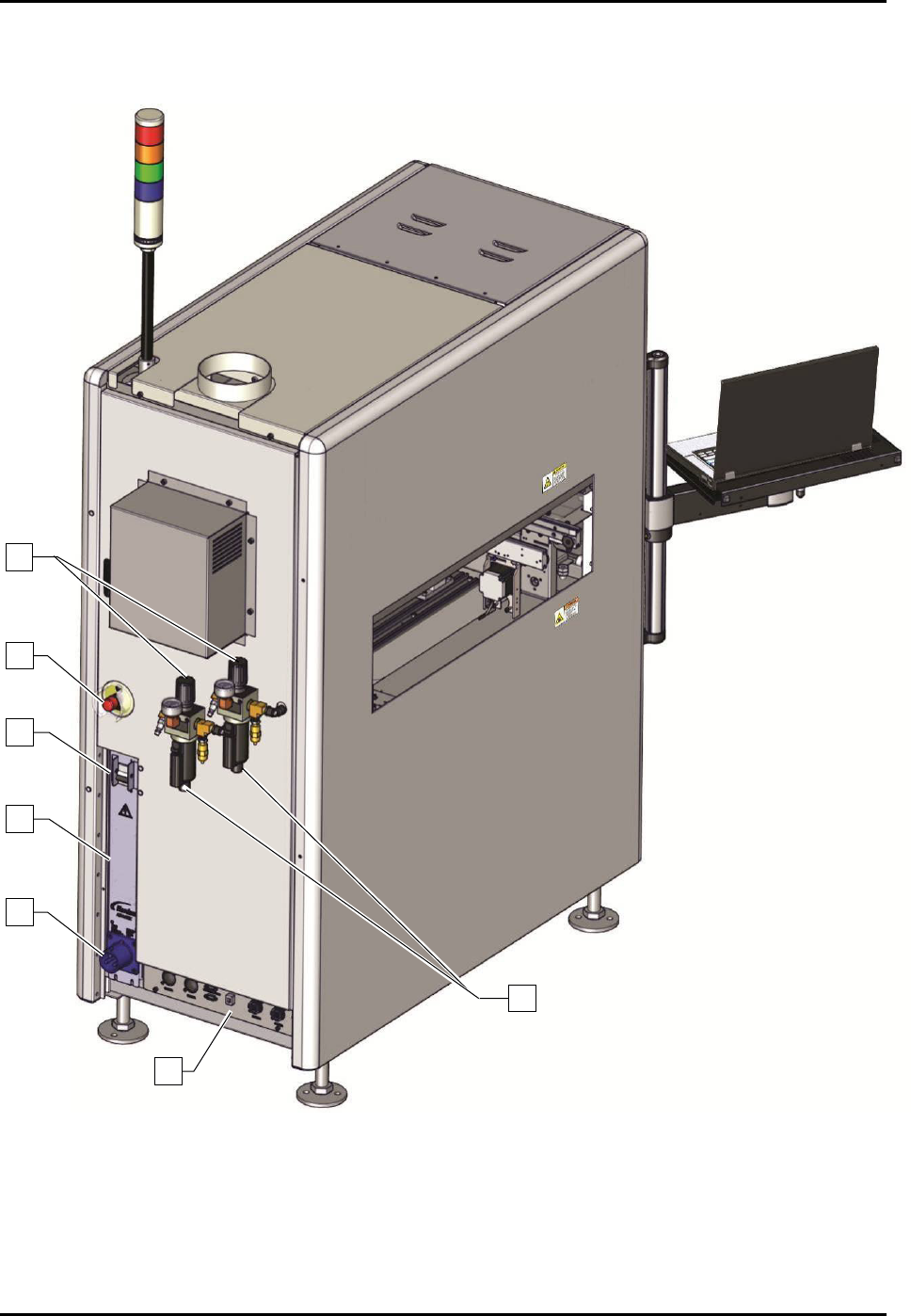
1.9.7 Rear View
Figure 1-10A Figure S2-9XXX Rear View (30A Power Manager shown)
2
3
4
5
6
1
7