Spectrum+Operating+Manual.pdf - 第150页
S2-9 XX X Se ri es Disp ensi n g Syst em IOM Man ual Troubleshoo ting 7-12 © 2023 Nordson Corporatio n Item Descript ion 1 Tact ile Sens or C ap 2 Tactile Sensor Figure 7-3 Tactil e Sensor Exposed 1 2

S2-9XXX Series Dispensing System IOM Manual Troubleshooting
© 2023 Nordson Corporation 7-11
7.4.12 Tactile Sensor
Table 7-12 Tactile Sensor Troubleshooting
Symptom Possible Cause Recovery
During setup routine,
error indicates that the
tactile sensor is already
engaged
Tactile sensor cap is stuck in the
down position.
Visually inspect the sensor cap for fluid buildup. If
there is fluid, clean the cap, see 7.4.13.1 Tactile
Sensor Error. If there is no fluid, contact Asymtek
Technical Support.
The tactile sensor signal can be tested from the
Fluidmove Tools > IO menu. Select IO and inputs.
Locate the tactile cap signal display and monitor its
state as the cap is depressed and released. If the
state does not change, the precision switch may
have failed.
Needle-to-height-sensor
offset is inaccurate
Fluid build-up on probe tip or
tactile sensor cap may have
caused inaccurate height sensor
calibration.
1. Clean probe tip/tactile sensor cap, see 7.4.13.1
Tactile Sensor Error.
2. Perform a “Valve Offsets” routine in Fluidmove.
For assistance, refer to the Fluidmove User
Guide or Fluidmove Online Help.
7.4.12.1 Tactile Sensor Error
If you receive a tactile sensor error, the following procedure may remedy the error.
NOTE If you continue to receive tactile sensor errors after performing the following procedure,
contact Asymtek Technical Support.
To remedy a tactile sensor error (Figure 7-3):
1. Gently lift the tactile sensor cap off of the tactile sensor.
2. Use isopropyl alcohol and a soft cloth to remove any residual fluid from around the
circumference of the cap, the tactile sensor opening and the sensor tip.
3. Replace the tactile sensor cap.
4. In the Main Window, click on
Tools.
5. In the Tools Window, click on
I/O Test.
6. Click on
Dispenser.
7. Locate the I/O for the tactile sensor.
8. Gently press down on the tactile sensor and make sure that the bit toggles
ON and OFF.
If the bit does not toggle
ON and OFF, the tactile sensor may need to be replaced.
Contact Asymtek Technical Support.
S2-9XXX Series Dispensing System IOM Manual Troubleshooting
7-12 © 2023 Nordson Corporation
Item
Description
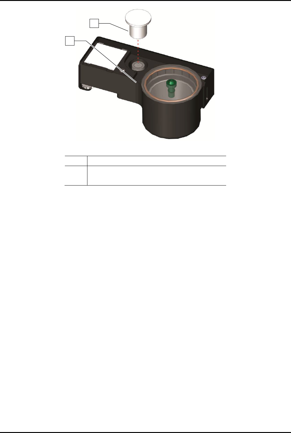
1 Tactile Sensor Cap
2 Tactile Sensor
Figure 7-3 Tactile Sensor Exposed
1
2

S2-9XXX Series Dispensing System IOM Manual Troubleshooting
© 2023 Nordson Corporation 7-13
7.4.12.2 Vision System
Table 7-13 Vision System Troubleshooting
Symptom Possible Cause Recovery
No Image
(Fluidmove display
window is a solid
pink color)
Camera not connected.
Verify camera cable is securely connected to the
connector on the top of the camera.
Faulty camera cable. Replace camera cable.
Camera LED is OFF
Camera not connected.
Verify camera cable is securely connected to the
connector on the top of the camera.
Faulty camera cable. Replace camera cable.
Camera LED
Steady Red
Camera not initialized.
It may take several minutes for the camera to acquire
a connection with the laptop. DO NOT attempt to run
Fluidmove or DALSA programs during this time.
Camera LED Slow
Flashing Red
Camera initialization problem.
1. Shutdown the computer and turn off power to the
machine.
2. Restart the machine, and then the computer.
3. If necessary, contact Asymtek Technical Support.
Camera LED Fast
Flashing Red
Camera overheated. Contact Asymtek Technical Support.
Camera LED Fast
Flashing Blue
Ethernet cable disconnected.
Verify ethernet cable is securely connected to the
camera and computer.
No Image
(Fluidmove display
window is dark or
black)
Lighting intensity is too low.
Increase light level in Fluidmove. Refer to the
Fluidmove User Guide or Fluidmove Online Help.
Lighting module disconnected. Restore lighting module connection.
Lens is blocked by foreign matter.
1. Remove and inspect the camera lens.
2. If necessary, replace lens, see 8.10.1 Replacing
the Camera Lens.
Lighting module is not functioning
properly.
Contact Asymtek Technical Support.
Unfocused image
Substrate is not within height
focus limits of the camera or the
lens is loose.
Adjust camera bracket, see 5.4 Focusing the
Camera.
Lens is damaged or there is
foreign matter on the lens.
1. Remove and inspect the camera lens, see 8.10.1
Replacing the Camera Lens.
2. If lens is damaged or dirty, contact Asymtek
Technical Support.
Inaccurate
dispensing after
moving or replacing
camera or lighting
module
Camera-to-needle offset is
incorrect and vision system
requires calibration.
1. Recalibrate camera, see 5.5 Calibrating the
Camera.
2. Perform a “Valve Offsets” routine in Fluidmove.
For assistance, refer to the Fluidmove User
Guide or Fluidmove Online Help.
No monitor display
Computer power switch OFF (0). Turn ON (I) computer power switch.
Monitor power or video cable is
not connected.
Verify that power and video cables are securely
connected to the back of the monitor.
Fluidmove vision
error encountered
during fiducial find
sequence.
Monitor power switch OFF (0). Turn ON (I) monitor power switch.
Corrupted vision file.
Re-teach the vision targets or entire program as
necessary.
Loose camera lens. Refocus the camera, see 5.4 Focusing the Camera.