Spectrum+Operating+Manual.pdf - 第68页
S2-9 XX X Se ri es Disp ensi n g Syst em IOM Man ual Installation 3-16 © 2023 Nordson Corporatio n To connect the syst em t o the facility air supply : CAUTION! Mak e sure that facility air pre ss ure meets th e requirem…
S2-9XXX Series Dispensing System IOM Manual Installation
© 2023 Nordson Corporation 3-15
3.13 Connecting the Power and Air Supply
Tools and Materials Needed
• Main Power Cable
• Facility Air Hose
WARNING! Make sure that your facility meets all requirements listed in 9.2 Facility
Requirements. Failure to meet these requirements could result in serious bodily
injury to personnel and damage to the dispensing system.
WARNING! This procedure should only be performed by a trained service technician.
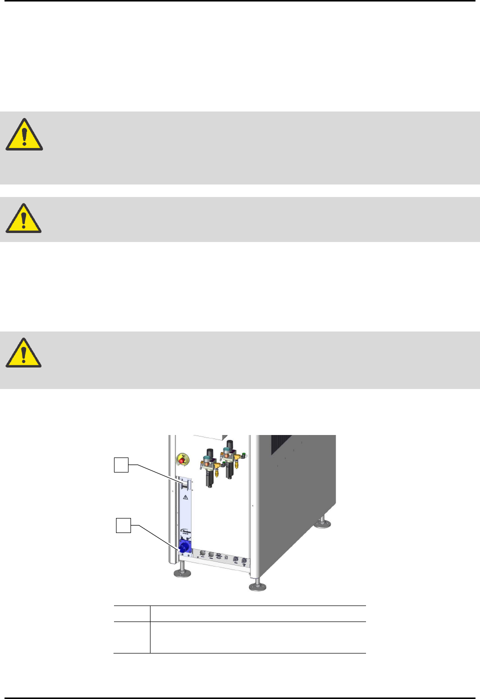
To connect the system to facility power (Figure 3-13):
1. Locate the main power cable, included in the accessories crate.
2. Plug the female end of the power cable into the main power inlet on the rear of the
dispensing system.
WARNING! Make sure that the main circuit breaker is in the OFF position before connecting
the dispensing system to the facility power source.
3. After making sure the main circuit breaker is OFF, plug the male end of the power cable
into the facility power source.
Item
Description
1 Main Circuit Breaker
2 Main Power Connection
Figure 3-14 Main Power Circuit Breaker and connection (30A Power Manager shown)
2
1
S2-9XXX Series Dispensing System IOM Manual Installation
3-16 © 2023 Nordson Corporation
To connect the system to the facility air supply:
CAUTION! Make sure that facility air pressure meets the requirements, see 9.2 Facility
Requirements. Higher pressures will damage the dispensing system.
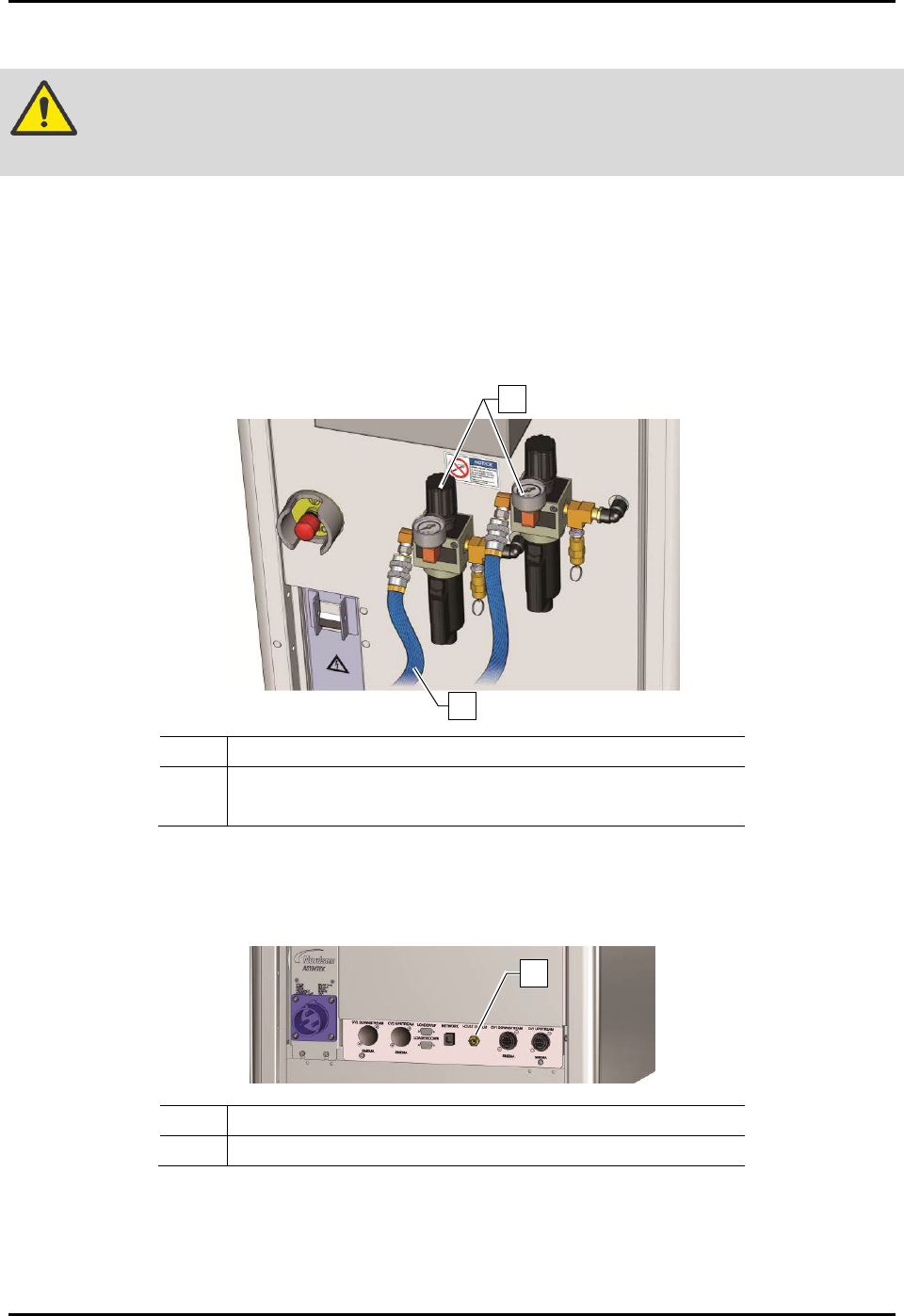
1. Locate the facility quick-disconnect air hose.
2. Make sure each dispensing system main air regulator is closed. Verify facility air pressure is
at 0 psi.
3. Connect the facility air hose(s) to the quick-disconnect(s) on the main air regulator(s).
4. If not already connected, also connect the air hose(s) to the facility air supply (Figure 3-14).
Item
Description
1 Main Air Pressure Regulator and Gauge Sets
2 Facility Air Hose
Figure 3-15 Connecting the Facility Air Supply
5. For S2-9XXC Cleanroom Systems only, connect the house vacuum to the facility air
(Figure 3-15).
Item Description
1 House Vacuum Connection
Figure 3-16 Connecting the House Vacuum (S2-9XXC)
1
2
1
S2-9XXX Series Dispensing System IOM Manual Installation
© 2023 Nordson Corporation 3-17
3.14 Adjusting the Main Air Pressure
The main air inlet provides regulated air pressure to the dispensing system from your facility air source.
You can adjust the main air pressure with the main air regulator.
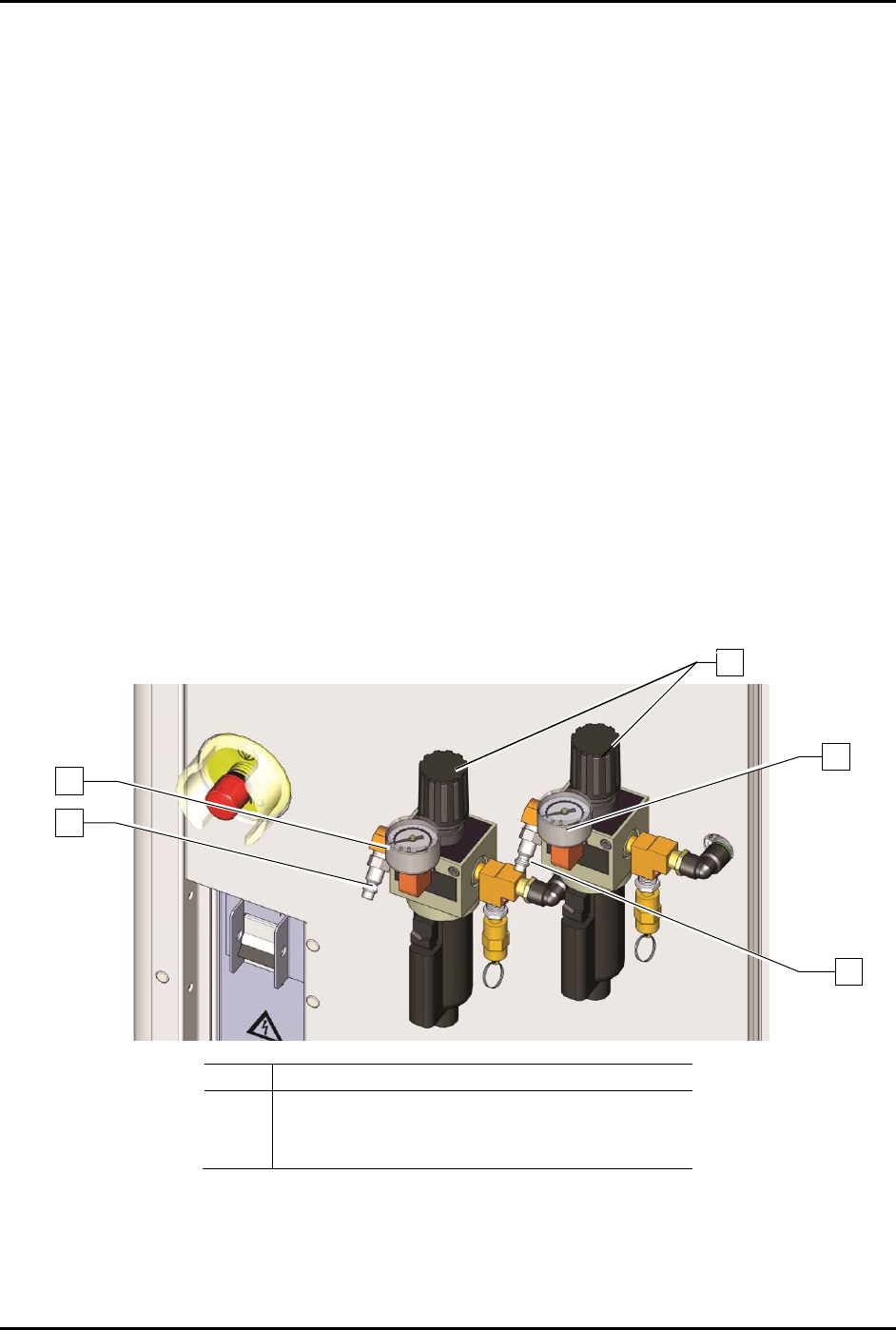
To adjust the main air pressure (Figure 3-16):
1. Verify that the facility air is connected to the main air pressure regulator inlet.
2. Locate the main air regulator at the rear of the dispensing system.
3. Rotate the main air regulator counterclockwise until the main air gauge registers zero (0).
4. Rotate the knob clockwise until the main air pressure gauge registers 621 to 689 kPa
(90 to 100 psi).
For accurate pressure adjustment, lower the pressure below the desired level and then
increase to the desired pressure.
5. If the main air pressure gauge fails to register pressure, verify that the dispensing system is
connected to the facility air source.
If there is an air leak, identify the source, shut off the
facility air, and fix the leak before
proceeding.
NOTE The regulator assembly is equipped with a relief valve to protect the system components.
Increasing the pressure above 655 kPa (95 psi) may trigger the relief valve. If so, reduce
the air pressure below 655 kPa (95 psi).
Item
Description
1
Main Air Inlet
2
Main Air Gauge
3
Main Air Regulator
Figure 3-17 Main Air Pressure Regulator and Gauge Sets
3
2
2
1
1