Spectrum+Operating+Manual.pdf - 第158页
S2-9 XX X Se ri es Disp ensi n g Syst em IOM Man ual Parts Replacement 8-6 © 2023 Nordson Corporatio n 8.11 Replacing the Dispense S tation Components Tools and Materials Needed : • Hex Key Set (Item 59) • B ubble Level …
S2-9XXX Series Dispensing System IOM Manual Parts Replacement
© 2023 Nordson Corporation 8-5
8.10 Removing and Installing the Dispense Station Cover
Tools and Materials Needed:
• Hex Key Set (Item 59)
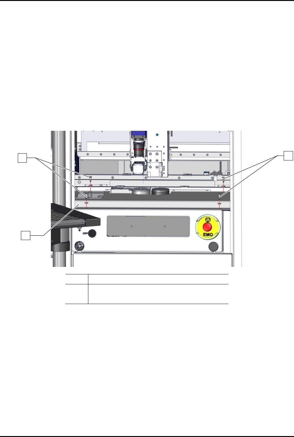
To remove the dispense station cover (Figure 8-2):
1. Perform a service shutdown, see 2.14 Service Shutdown.
2. Open the dispensing area door.
3. Remove the four (4) screws and four (4) washers securing the dispense station cover to the
dispensing station.
4. Remove the dispense station cover from the dispensing system.
Item Description
1 Screws and Washers (4 ea.)
2 Dispense Station Cover
Figure 8-2 Replacing the Dispense Station Cover
To install the dispense station cover (Figure 8-2):
1. Secure the dispense station cover to the dispensing system with four (4) screws and four (4)
washers.
2. Close the dispensing area door.
1
1
2
S2-9XXX Series Dispensing System IOM Manual Parts Replacement
8-6 © 2023 Nordson Corporation
8.11 Replacing the Dispense Station Components
Tools and Materials Needed:
• Hex Key Set (Item 59)
• Bubble Level
• Torque Wrench
8.11.1 Replacing the Service Station
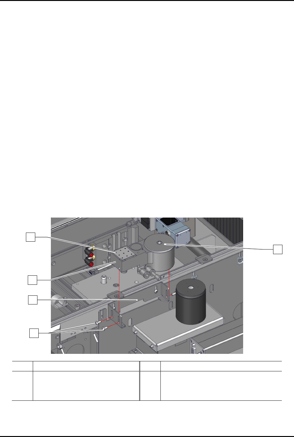
To remove the service station (Figure 8-3):
1. Perform a service shutdown, see 2.14 Service Shutdown.
2. Open the dispensing area door.
3. Remove the dispense station cover, see 8.8 Removing and Installing the Dispense Station
Cover.
4. Remove the dispensing station cover from the dispensing system.
5. Remove the dispense tile and purge station lid from the service station.
6. Disconnect the pneumatic
and electrical connections from the service station.
7. Loosen, do not remove, the three (3) screws securing the service station to the service
station bracket.
8. Remove the service station from the service station bracket.
Item
Description
Item
Description
1 Dispense Tile 4 Service Station Bracket
2 Purge Station Lid 5 Service Station (Item 44)
3 Screws (3)
Figure 8-3 Replacing the Service Station
1
2
4
5
3

S2-9XXX Series Dispensing System IOM Manual Parts Replacement
© 2023 Nordson Corporation 8-7
To install the service station (Figure 8-3):
1. Remove and set aside the dispense tile and purge station lid.
2. Place the service station into the service station bracket.
3. Place a bubble level onto the service station.
4. Adjust the service station height, see 5.11 Adjusting the Service Station Height.
5. When level, tighten the three (3) screws securing the service station to the service station
bracket.
If needed, fine leveling can be
achieved by adjusting the set screws on the service
station.
6. Remove the bubble level from the service station.
7. Reinstall the dispense tile and purge station lid.
8. Connect the pneumatic and electrical connections to the service station.
9. Install the dispense station cover, see 8.8 Removing and Installing the Dispense Station
Cover.
10. Close the dispensing area door.
8.11.2 Replacing the Scale Assembly
To remove the scale assembly:
1. Perform a service shutdown, see 2.14 Service Shutdown.
2. Open the dispensing area door.
3. Remove the dispensing station cover, see 8.8 Removing and Installing the Dispense Station
Cover.
4. Remove the dispense station cover from the dispensing system.
5. Remove the service station, see 8.9.1 Replacing the Service Station.
6. Remove the scale lid, scale cup, breeze shield cover, and scale pedestal from the scale
(Figure 8-4
).
7. Remove the two (2) screws securing the service station bracket to the rail.
8. If a scale shutter is installed, disconnect the pneumatic connections from the scale assembly.
9. Disconnect the electrical connection from the scale assembly.